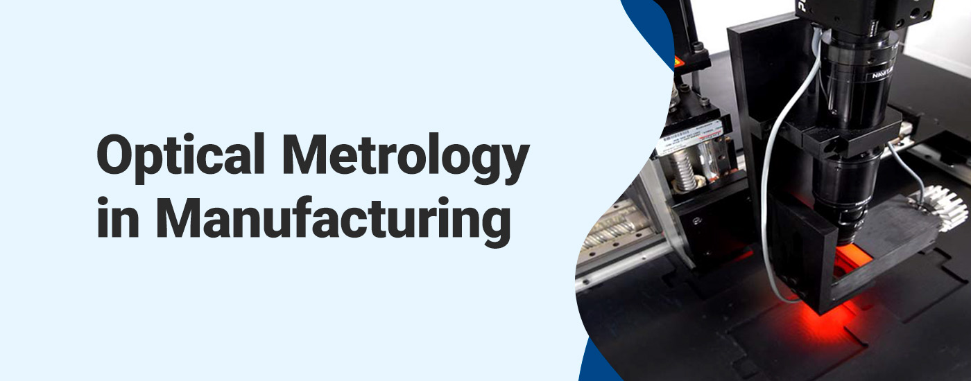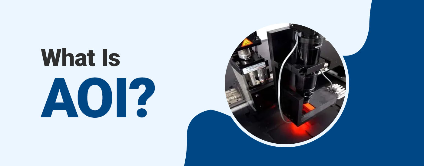
Automated optical inspection (AOI) technology is used in manufacturing processes to detect defects and ensure inspected products are of the highest quality. The system utilizes cameras and computer vision algorithms to inspect components, assemblies, printed circuit boards, and other parts for discrepancies in terms of soldering, component placement, and other manufacturing defects.
Optical inspections performed manually can miss minor imperfections as a result of human error. The precision and efficiency of AOI eliminate this concern, and when combined with automated reporting of results, it makes AOI an invaluable addition to any modern manufacturing facility. As a result, this technology has become an essential tool in enhancing quality control processes across a diverse range of industries, particularly in electronics manufacturing.
The quality of the images an AOI system can produce determines the accuracy of product inspections. There are three vital components that comprise an AOI system and facilitate its ability to detect product flaws:
Light source: The light source illuminates inspected products. This component directly influences the quality and accuracy of image capture and defect detection. Appropriate lighting conditions enable the cameras to highlight features, detect subtle defects, and enhance contrast for clearer imaging. Various AOI systems use different types of light sources depending on the intended application. Most modern systems use LED arrays and halogen lamps. These provide consistent illumination for thorough examinations.
Lenses: The lens directs the light reflected off the product into the camera sensor. AOI systems use premium-quality lenses to capture sharp images. A lens system can be adjusted to change the depth and field of view, making it possible to inspect different types and sizes of products.
Camera: The third component is the digital camera that captures the product’s image. Different systems may use a standard 2D camera or a sensor that captures rotational images for a 360-degree view of the part.
Types of AOI
Optical inspection needs vary, so there are multiple types and configurations of AOI systems available.
Inline AOI
Inline AOI is a quality control process where the AOI system is integrated into the manufacturing line, allowing product inspections to occur in real time. With inline AOI, inspection times are limited because the evaluations must be completed as the products move through the production line.
Online AOI
Online AOI refers to inspection stations located within the manufacturing line but not directly integrated with it. Components are inspected as they move along the assembly line, but the inspection process may or may not halt the line if a defect is found. Online AOI systems are commonly used for inspecting randomly selected samples and are therefore ideal for high-speed production. Software like VisionGauge® OnLine provides additional tools and features to enhance online AOI effectiveness.
Offline AOI
Offline AOI systems inspect components and products outside the production line. This approach allows goods to be inspected in a separate, controlled environment. Choosing an offline AOI system often means slower output but enables more detailed and comprehensive inspections without time constraints.
2D AOI
The most common type of AOI system is two-dimensional AOI. These systems utilize 2D cameras to take photos of items for inspection and represent the most effective method for detecting surface-level defects. Incorrect or missing components, misalignments, and soldering defects are easily identifiable using this setup.
3D AOI
Three-dimensional AOI systems are a more advanced version of this technology. These scanners may produce a 360-degree rendering of the item, using sensors instead of cameras to create topological maps of the inspected components or products.
Benefits of AOI
Building an automated AOI system into a manufacturing line affords an operation numerous advantages:
More accurate inspections: Because AOI provides detailed images and scans of components, these systems can pick up the tiniest defects or deviations from production standards. This technology can perform ultraprecise measurements to confirm dimensional accuracy.
Enhanced productivity: These machines can operate at high speeds, completing thousands of inspections per hour. AOI systems are valuable assets for high-volume manufacturing and production facilities.
Cost savings: Manufacturers can reduce their production costs by finding defects early, allowing them to avoid unnecessary expenses like recalls or material waste. Using AOI equipment also has the potential to reduce customer complaints related to the release of defective goods.
Reduced downtime: Utilizing an AOI system can significantly reduce overall production time, especially when replacing manual inspection as the chief source of quality control operations. Eliminating a potential bottleneck in quality assurance allows manufacturers to accelerate the flow of products to market.
Limitations of AOI
While AOI systems provide a lot of value, manufacturers do need to be aware of a few factors before they make the initial investment in this technology:
Special setup requirements: Setting up and programming AOI equipment can be an intricate process requiring a specialist with in-depth knowledge and training. Because of the steep learning curve, it could be extremely challenging for a layperson to install and program this technology correctly.
Difficulty in adapting to new versions: AOI systems are rigid, but line processes tend not to be. AOI is far less effective in situations that involve rapid product changes, as inconsistency in the scanned objects could make it difficult to identify defects correctly. An AOI system generally must know exactly what is working with and is looking for at all times.
Programming demands: AOI equipment must be programmed on-site, and unless the programming is transferrable, it can only be done on one machine at a time. For larger setups, this could cause major delays, especially when frequent changes must be made.
Inability to detect new issues: While AOI equipment can find a large variety of defects, it can only identify the defects it is instructed to find, such as dimensional errors or a flawed surface finish. Consequently, new, unexpected issues could pass through inspection undetected.
Due to the limitations of AOI technology, it is best suited for established products and manufacturing lines where any potential issues are already known and the design is unlikely to see frequent changes. In these scenarios, the speed and accuracy improvements it provides yield an excellent return on investment.
How to Integrate an AOI System Into a Production Line
Integrating an AOI system into a manufacturing process involves several key steps:
Assess system requirements: Understanding the specific requirements of the production line is important. Consider the types of defects that need to be detected and the desired level of inspection accuracy.
Select the right AOI system: Make sure the AOI system you choose aligns with the intended production line. Consider factors like whether you need 2D or 3D inspections and how quickly you need the products to move through the quality assurance phase.
Prepare the production line: Ensure the production line is ready for AOI integration. Review the workflow and set up appropriate conveyor systems or interfaces to keep products moving seamlessly through the inspection station.
Employee training: Provide training to employees and operators to ensure they know how to maintain the AOI system. You’ll also need to train personnel in interpreting and responding to inspection results.
Trust VisionGauge® With Your Production’s Integrity
VisionGauge® AOI systems feature advanced engineering to suit your production needs, whatever they may be. VisionGauge® machines provide you with a variety of manual or fully automatic inspections, precise part measurements, and excellent quality control, and we back them with exemplary application support. Our team specializes in creating powerful, intuitive technology to support production operations across diverse industries.
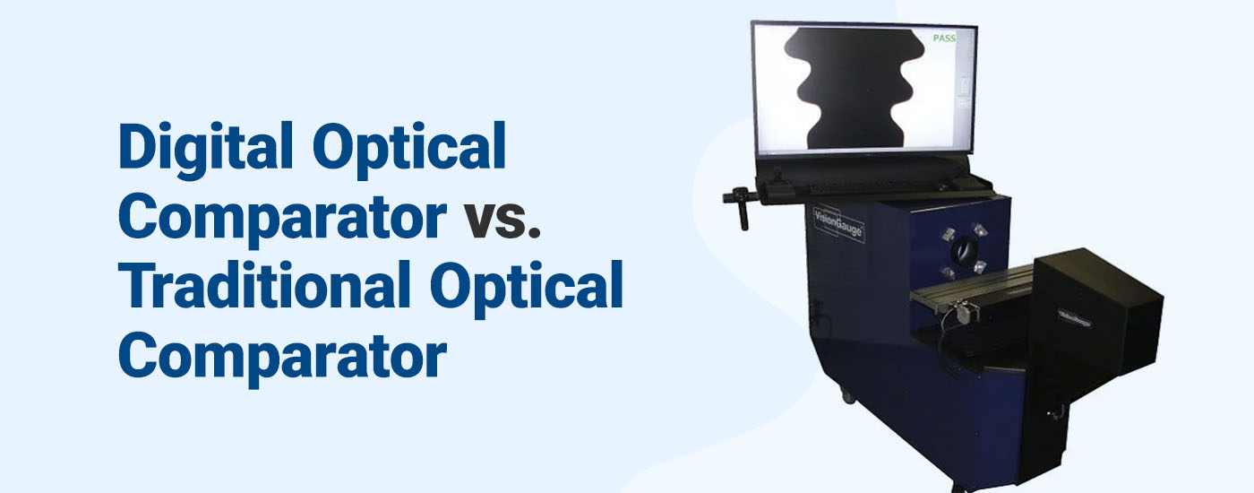
Digital Optical Comparator vs. Traditional Optical Comparator
Optical comparators are innovative tools used throughout manufacturing applications to inspect, measure, and compare the specifications of various manufactured parts. These machines use high-quality lenses and mirrors to magnify a component’s silhouette onto a screen and allow for an in-depth examination, checking for defects and inaccuracies.
Optical comparators are available in both traditional and digital configurations. Manual comparators are straightforward and valuable in smaller applications but lack the efficiency and strength to keep up with large-scale production cost-effectively. These tools can only produce 2D renderings of simple parts one at a time, making them quite labor-intensive.
Instead, more operations are turning to advanced digital optical comparators for streamlined work and enhanced accuracy.
What Are the Benefits of Digital Optical Comparators?
Digital optical comparators allow professionals to obtain precise and dependable measurements of their products, resulting in higher-quality production output. They use high-quality digital cameras, sophisticated software, and unique lighting techniques to analyze simple and complex parts, complete with practical 3D capabilities.
Other benefits of digital optical comparators include:
Accuracy
Digital optical comparators are highly accurate devices delivering precise measurements and comparisons. Using advanced digital image processing and innovative computations, these systems can make corrections to enhance overall image quality. They can correct 2D non-linear distortion while performing other enhancements like sharpening edges and reducing noise to create a high-quality image.
While many traditional tools use templates and overlays, which tend to distort and stretch over time, these machines work with existing CAD plans for precise part comparisons. Digital optical comparator software also features sub-pixel edge detection technology to locate edges between pixels for ultra-precise results with minimal human error.
Usability
Digital tools streamline quality control and inspection procedures. They are quickly installed within various environments, allowing operators to incorporate them easily directly into their operations. Their small footprint optimizes floor space, and their mobility supports fast and efficient inspections throughout your location without needing re-calibrations in-between.
Digital versions use lenses with much larger depths of field, allowing the system to keep everything in focus while conducting inspections. This feature eliminates the need to refocus when continuously analyzing different sections of a specific part. Since this happens automatically, multiple parts can be examined without human participation, reducing labor costs while increasing throughput.
Due to their ease of use and convenience, these tools are widely used throughout numerous industries, such as:
Aerospace
Machining
Military
Power
Energy
Automotive
Telecommunications
Automation
Digital optical comparators are fully automated devices used with intuitive tools, such as the VisionGauge® patented CAD Auto-Pass/Fail™ and CAD Auto-Align™ systems from VISIONx, Inc. These tools make the VisionGauge® Digital Optical Comparator completely independent from operator to operator to increase the dependability and repeatability of the results. Here’s more information regarding these tools:
CAD Auto-Pass/Fail™: VisionGauge® Digital Optical Comparators deliver automatic reports, charts, statistics, and much more. This tool can determine whether a part is within tolerance, removing any operator subjectivity.
CAD Auto-Align™: This tool creates the best fit for the CAD by automatically aligning it to the part along the datums. It travels down the length of small and large parts, even across multiple fields-of-view, to collect imaging in different locations and provide information that matters.
Learn More About Digital Optical Comparators From VISIONx
VISIONx specializes in producing state-of-the-art automated imaging, visual inspection, and high-accuracy measurement solutions you can trust. We have created numerous digital optical comparator models capable of improving your site’s specific productivity and performance needs. With our patented VisionGauge® Digital Optical Comparator, you’ll ensure your products are within spec and avoid production flaws more easily than ever.
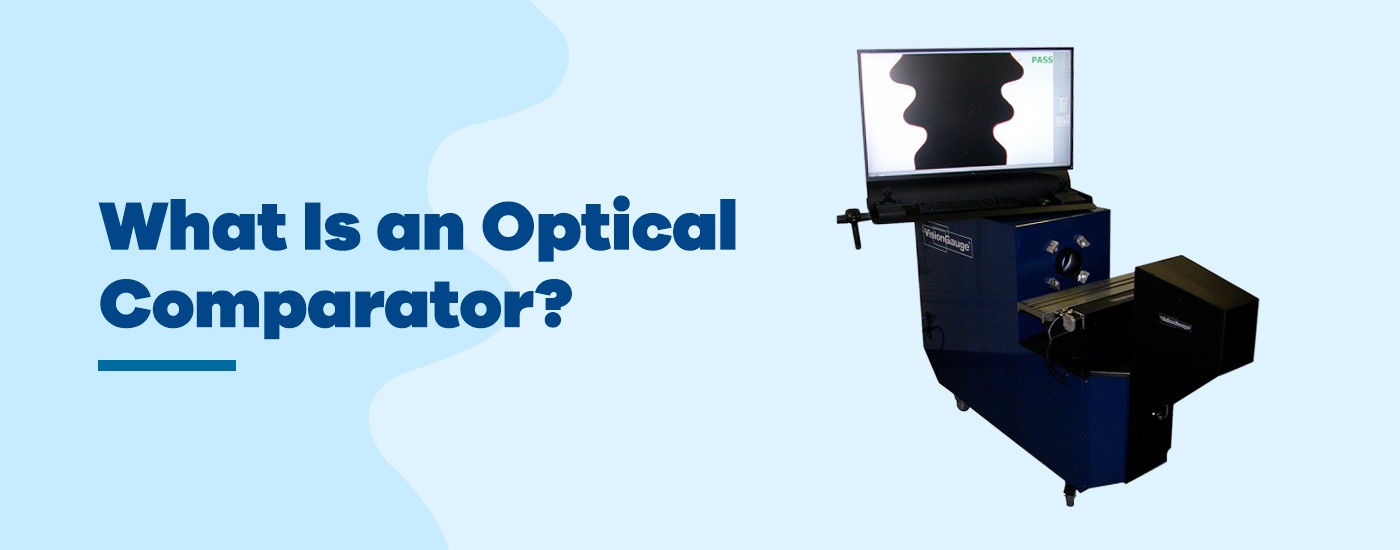
Also known as profile projectors, optical comparators are used in various industries to measure, analyze, and inspect manufactured parts and compare them to their design specifications. This process of comparing the existing part to its prescribed limits helps ensure parts fall within tolerance before use and that they are not overused or damaged. Comparators use lights, mirrors, and lenses to magnify a part and display the image on a screen for viewing.
Comparators can vary in a few ways, and the best type of optical comparator for your application will likely depend on your needs, including the parts themselves and your inspection requirements. Find out how to determine the best optical comparator with this guide.
Choosing the Right Type for Your Application
When choosing an optical comparator, you have some decisions to make regarding features that would best suit your application. Optical comparators can come in two configurations — vertical and horizontal — which is how the light shines on a part. In vertical optical comparators, the light shines vertically on the part so that the operator is looking down on it. In contrast, horizontal comparators provide a silhouette of the side of a part.
Both configurations can be used to inspect parts in various industries, ranging from manufacturing to aerospace. Ultimately, the configuration you choose will depend on the parts you’re inspecting.
Traditional vs. Digital
One of the biggest decisions to make is whether you’ll choose a traditional or digital comparator. Both types have their place in machinery inspection, though one is more efficient than the other.
The traditional optical comparator has had close to the same design since the birth of this technology in the 1920s. Traditional comparators require an operator to line a part up with a mylar overlay that serves as a guide for manual comparison. After aligning the overlay with the part, the operator determines whether the component can still be used if there are discrepancies. Overall, traditional comparators are fairly easy to use, though the manual process is slow and less accurate.
As technology advanced, comparators saw a digital shift. Digital optical comparators make the inspection process significantly more streamlined and precise. Instead of an operator taking measurements manually, parts are automatically compared directly with their CAD drawings to get a precise comparison. The automated process also can inspect multiple pieces at once, making the job much more effective.
Because digital comparators allow operators to inspect multiple parts simultaneously, they’re typically a more efficient option for applications requiring regular inspection of many parts. Both types of comparators have their worth in certain applications, and the best optical comparator for you will depend on your industry’s demands.
Accuracy
As machinery becomes more advanced and parts become more specific, the need for more accurate inspections and comparisons increases. The more complex machine parts become, the harder it becomes to complete accurate comparisons with a traditional comparator. In some cases, manual comparisons cannot reach the necessary level of accuracy. In these applications, a digital comparator is often required to ensure the most accurate comparison.
While traditional comparators can still be accurate, there is also a risk of human error. Without highly trained comparator operators, some companies are likely better off with the automated accuracy of a digital comparator.
Optical Comparator Accessories and Characteristics
While traditional and digital comparators are used for many of the same jobs, some differences in their characteristics may help you decide which is best for your application. Let’s look more closely at some defining characteristics of optical comparators of each type.
One of the most significant traits of traditional optical comparators is the need for physical overlays. Most commonly made of mylar, overlays are printed with CAD charts, grids, angles and more. Overlays serve as a comparison guide for the operator, allowing them to take measurements of parts. The comparator only projects 2D images of elements, limiting the operator to inspecting less complex components in one view.
Traditional comparators also require time-intensive manual labor. These comparators only measure parts one at a time, which can be incredibly time-consuming. They typically only come with one magnification, though additional lenses can be purchased.
Digital optical comparators typically offer a lot more. They provide automated rotation for views of parts in multiple lighting modes. Because they are automated, they rely on software and cameras to quickly and precisely analyze parts. This feature allows these comparators to automatically analyze several parts at once without help from a human operator.
One of the best aspects of digital comparators is that all the CAD drawings for your parts can be uploaded and saved in the software, so there is no need for mylar overlays. The software also allows you to save and store analysis reports and documentation, keeping everything in one place.
Choosing a Reliable Manufacturer
Another important aspect of finding the best optical comparator is choosing a reliable manufacturer. A reliable comparator manufacturer will consistently work to improve their products. Whether it’s timely updates to the software, remote support when a problem arises, or application support to start inspecting a new part, be sure you’re purchasing an optical comparator from a manufacturer that will support you after your purchase.
Technical Support
A reliable manufacturer will provide remote technical support. Support from anywhere in the world lets you contact the company if you’re having an issue with their product. They may ask you to walk them through the problem over the phone or even access your system remotely to explore and solve the issue themselves. Make sure you choose a comparator from a manufacturer that will take the time to help you get back to the task at hand without major downtime.
Application Support
Application support involves training and support related to using the product effectively for a given function. Reliable manufacturers want to ensure their customers know how to use their products in any field where the solution is being applied. Comparator manufacturers that offer their products to various industries should understand how the comparator works within each sector to help with setup and training for new users so they can confidently solve their applications.
Use the VisionGauge® Digital Optical Comparator for Your Inspections
We specialize in optical solutions that provide high-accuracy measurements. All of our systems and products are powerful and easy to implement, and you can find our devices in labs, production floors, and industrial facilities around the world. We’re dedicated to providing prompt support alongside our products so you can use them effectively.
The modern manufacturing industry relies heavily on optical inspection to verify parts are meeting compliance standards. This procedure uses optical comparator technology to compare a part to its computer-aided design (CAD) file. Optical comparators have been around since the 1920s, and the modern units’ operations are still similar. However, as technology advances, the need for physical optical comparator mylar overlays is diminishing.
This guide will explain why mylar overlays are essential to traditional optical comparators, and how digital optical comparators are eliminating the need for mylar overlay charts.
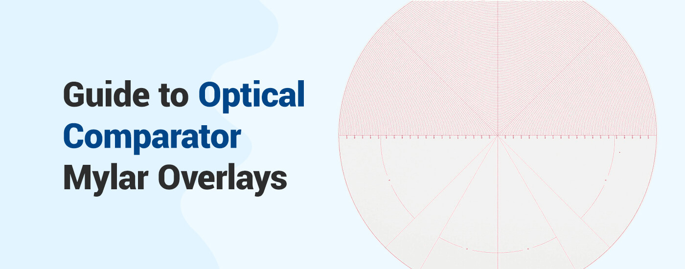
Mylar overlays are transparent charts that are used to manually compare a machine’s part with its CAD drawing. Optical comparator overlays serve as a guide for comparison. They help the optical comparator operators take measurements of a given part and determine if the part’s critical dimensions are within specifications or if the part has sustained any damage and should be replaced.
An operator turns on the optical comparator and places the desired part in the staging area to be observed.
Once the image is displayed, the operator places the corresponding overlay on the screen and physically aligns it with the projected image of the part.
Finally, the operator manually compares the CAD drawing on the overlay to the part’s image. If there are any discrepancies identified in the part, the operator has to determine if it is still within tolerance to operate safely.
How to Choose a Mylar Overlay
The optical comparator overlays you choose will depend on a few aspects of your project needs:
1. Style of Chart
In addition to mylar overlays with CAD charts on them, overlays can be printed with different grids or angle measurements. These overlays are used to take precise measurements of a part’s radius or angles. These other styles of overlay charts can be as simple as a four-quadrant grid or as complex as charts for checking a screw’s thread forms. Other charts can be printed with 360-degree protractor lines or angle measurements of your choice — or even a combination of the two.
2. Type of Optical Comparator
When ordering an overlay, you’ll want to specify what model and type of comparator you’ll use the overlay with. Some optical comparators are compatible with specific materials, overlay sizes, or thicknesses.
3. Lens Magnification
It’s essential to consider the magnification you’ll be viewing the images or CAD files at. If the overlay is printed with the wrong magnification in mind, the operator will be unable to take accurate measurements or make an accurate assessment of a part. The magnification scale can also vary depending on the machine, the overlay manufacturer, and the material used.
4. Overlay Material
Optical comparator overlays can be made of various materials. The most common material is a mylar sheet. Overlays can also be made with plastic or vinyl. Different materials will have different thicknesses, which could affect how the overlay works with the optical comparator. It’s also common for overlays to have either a frosted or clear finish, affecting the visibility of a chart on the projector.
Digital Optical Comparators
Digital optical comparators are becoming increasingly popular and necessary as machinery gets more advanced. Digital comparators are far more efficient because they eliminate the need for mylar overlays.
Traditional mylar overlays are easily damaged, especially when handled frequently. Because of the sheer number of overlays needed for each piece of machinery, storage for the overlays requires a significant amount of space. This also means that if an overlay is misfiled, locating it can be time-consuming, which delays the inspection process. Mylar overlays are expensive to make, and when product designs change, the cost of replacements can add up quickly.
A digital optical comparator uses digital CAD charts and an internal projector to display a part’s image. The virtual charts can automatically adjust to changes in magnification — an operation that would normally require the overlays to be physically changed. Also, digital CAD charts can be automatically aligned on a part, automatically compare the part to the overlay, and can stay aligned as a part moves by automatically tracking/moving with the part. Since the digital CAD charts are used directly, when designs change, there’s no need to make a new mylar overlay. CAD files can be limitlessly imported and easily accessed and stored on a secure network, making the automatic part comparisons that much faster.
Digital Optical Comparator Benefits
Digital optical comparators, like the VisionGauge® Digital Optical Comparator, can benefit many manufacturing industries, including medical and orthopedic, automotive, biomedical, electronics, telecommunications, power and energy, and more. Some essential benefits include simplified use, improved accuracy, and full automation:
1. Simplified Use
If you thought traditional comparators were easy to operate, digital optical comparators are incredibly simple to use in comparison. The operator only has to complete one step — position the part on the staging area. The digital optical comparator’s advanced software takes care of the rest. Digital comparators work directly with CAD files, which eliminates the need for tedious overlays or templates. Without the need for overlays, the process becomes simple and automated.
2. Improved Accuracy
Because they are digital, these optical comparators are exceedingly accurate. The automation of the digital optical comparator functions eliminates the potential for human error when taking detailed measurements. Digital comparators are also equipped with software that provides detailed documentation of statistics, measurements, and a record of pass/fail results. This information is then safely stored on a secure network.
3. Fully Automated
One of the most significant benefits of digital comparators is that they are fully automated. Using fast software and cameras, digital optical comparators analyze and measure parts automatically. Within seconds, the system aligns the part with its CAD drawing and compares the two. The automatic functions allow operators to increase throughput with fast comparisons.
4. Additional Benefits
More benefits of the VisionGauge® Digital Optical Comparators include:
Eliminate the need for optical comparator overlay charts
Highly reliable
Support for automated rotation for multiple views of the same part
Automatically analyze multiple parts
Choose VisionGauge® Digital Optical Comparators
At VISIONx, Inc., our goal is to help your company’s inspection process become accurate, fast, and effective. VisionGauge® Digital Optical Comparators can help you streamline measurement and verification processes so your employees can quickly complete more tasks with high accuracy and reliability. Our operator-independent technology allows for a wide range of automatic results.
In addition to our state-of-the-art optical comparators, we also develop, sell, and support software, hardware, and other systems for all your inspection, measurement, and imaging needs. No matter what industry you’re in, you can rely on VISIONx, Inc. for standard or custom solutions. Browse our available products or contact us for more information today.
The optical comparator (profile projector) has been used in quality control in the manufacturing industry since it was first patented in 1925. The overall design has changed little in that time, with the exception of some digital and software enhancements. The continuing popularity of this device is a statement of how useful it is for optically checking parts for conformance and deformities.
Here we will discuss what comparators are, as well as the following questions: what is an optical comparator used for, how does it work, and how do traditional models compare to digital ones?
Optical comparators, also called comparators or profile projectors, are measurement tools used in the manufacturing industry. Comparators inspect, measure, and compare the dimensions of manufactured parts. These measurement tools function using the principles of optics by utilizing illumination, lenses, and mirrors to project a magnified silhouette of a part upon a screen. Doing this compares the part to its prescribed limits.
Optical comparators are used to check for both dimensional accuracy and surface defects, such as scratches and indentations. In short, they allow for non-contact measurement and observation, minimizing handling while still allowing for close inspection.
Horizontal comparators: In a horizontal model, the optical comparator’s light travels horizontally so the viewer is looking at a silhouette taken from the side of a part. This model works best for parts held in a fixed location — some examples include screws that are fixed in place or castings that must be held in a vise.
Vertical comparators: In a vertical model, the optical comparator’s light travels vertically so the viewer is looking down on the part. This works best for flat components that can lie on the work stage, such as gaskets. They also work well on flexible or soft elements that need to lie on a flat surface to provide an accurate measurement.
Optical comparators of both types can be found in manufacturing shops and lab environments related to quality control. They are most popular in industrial sectors, including the scientific, automotive, medical manufacturing, aerospace, and defense industries.
How Does an Optical Comparator Work?
Optical comparators have changed little since they were invented in the 1920s — the reason for this is that the technology uses optics, which have only changed in quality, not function. Optical profile projectors work similarly to overhead projectors commonly used in classrooms. A light is directed through a stage to a series of lenses and mirrors, which then project the silhouette of whatever is on the stage onto a screen.
Optical comparators use this same principle. A part is affixed to a stage and a light source shines on it, resulting in a shadow image of the part. The shadow is magnified with lenses and bounced by mirrors onto the back of a screen. This screen is fixed at a known distance for measurement purposes.
Optical comparators can vary in the size and magnification of the projected image. Both of these metrics depend on the optics and screen size of the comparator. Screen sizes for optical comparators range from 12 to 36 inches, though models with larger screens are available. However, larger screen sizes are only possible with larger enclosures, as a greater distance is required to generate a bigger image without distortion.
Another way that optical comparators differ is in the measuring processes they use. There are three different measuring processes for comparators:
Silhouette measurement: The simplest measurement method is to project a silhouette of the image onto a screen for measuring. Because the magnification is known, the silhouette can be used to gain accurate measurements.
Point comparison: The second measurement method is to compare the image’s silhouette to prescribed plan points on a screen. The part’s silhouette is centered on the screen and the user moves the stage to hit various points on the screen. This measures how much the stage had to move to match the part to the point.
Software analysis: The last measuring process is digital, using software to analyze and measure the image generated by the optical comparator.
The first two methods are used by traditional optical comparators and are the most common in the industry. The third is employed by digital optical comparators, which handle the entire process electronically.
How to Use a Traditional Optical Comparator
Using an optical comparator with a traditional setup, the steps are similarly simple:
Placement: First, the operator must turn on the optical comparator and place the part to be observed on the staging area.
Alignment: When the part’s image is projected on the comparator’s screen, the operator must place an overlay on the screen. The optical comparator overlay, also known as a template or Mylar, is a part drawing printed on a transparent overlay that is scaled to match the magnification of the comparator. The operator must align this overlay with the part’s image.
Comparison: Once the overlay is placed, the operator compares the drawing to the image and identifies any discrepancies. From these discrepancies, the operator will determine if the part is within tolerance.
This is the process used for most traditional optical comparators, though there are various methods available for this technology. For example, instead of an overlay with a part plan, an overlay may feature a grid or concentric circles to allow for more precise measurements of a part. Alternatively, a point comparison method may be used, where the image’s silhouette is centered on the screen compared to an overlay. The user then moves the stage to hit prescribed points on the overlay, measuring how much the stage had to move to match the part to each point.
Limitations of Traditional Optical Comparators
Profile projectors are generally straightforward and require little training to use. Traditional optical comparators that use silhouette measurement or point comparison simply require the user to fix a part in place and observe the on-screen image.
While traditional optical comparators are easy to use and operate, they also present disadvantages because of their simplicity. Some primary flaws of traditional optical comparators include the following:
Limited complexity required: Production parts are becoming more complex, and observing them at more than one angle is becoming increasingly necessary. However, traditional comparators don’t accommodate this well.
Less accurate: How accurate is an optical comparator? Although traditional optical comparators can obtain very accurate measurements, today’s modern parts require tighter tolerances, reducing the room for error that is allowedwith any manual measurement method.
Labor intensive: Traditional optical comparators can only measure one part at a time. This poses a problem when needing to inspect large quantities of parts, as is often needed in the manufacturing industry. This is particularly the case when inspecting large quantities of parts at once, since a vision system can allow you to place multiple parts for inspection on the stage at the same time.
2D limitations: Traditional optical comparators can only project 2D images onto a screen, which can present issues for analyzing multiple dimensions at once.
Although these limitations present no issues for non-repetitive tasks used to analyze 2D parts, anything outside of this defined operating bubble is an obstacle for traditional optical comparators. For large-scale, complex analysis, a different model is necessary.
Digital Optical Comparators vs. Traditional Optical Comparators
Where traditional optical profile projectors fall short, digital models pick up the slack. Manual comparator technology is highly useful in small-quantity applications, but with the rise of more complex parts and large-scale manufacturing, automation is necessary. Digital optical comparators present the solution.
Digital optical comparators offer the following advantages:
Automation capabilities: These models use software and cameras instead of human eyes to analyze and measure parts. The software automates the measuring process and completes it more quickly than a human can.
3D capabilities: Digital optical comparators can use multiple lighting techniques and 3D inspection methods to analyze parts in all three dimensions.
Quantity management: The automated nature of digital optical comparators means they can analyze multiple parts automatically without human intervention.
Accuracy: By removing the potential for human error, digital optical comparators are extremely accurate in their measurements, which is necessary for many modern industries and technologies.
Using Traditional Optical Comparators vs. Using Digital Optical Comparators
While traditional optical comparators are generally straightforward to use, they present significant disadvantages to both users and clients. Some of the most significant drawbacks include:
Little quantifiable data: Measurements using traditional comparator methods can be subjective and difficult to quantify. When comparing a part to an overlay with a plan, the goal is simply to pass or fail the part. However, clients are increasingly asking for quantifiable data about each deviation, which is difficult to achieve with this method.
Limited flexibility: Traditional optical comparators only project 2D images onto a screen. This presents an issue in an industry where parts are becoming increasingly complex and require analysis from multiple angles. With a traditional optical comparator, an operator analyzing a complex part must physically move the part and utilize multiple overlays for analysis, which can be difficult depending on the part’s geometry and requires a significant input of time and labor.
Reduced accuracy: Today’s parts require tighter tolerances and more quantifiable data. Although traditional optical comparators are capable of gathering accurate measurements, this requires a highly trained operator. Additionally, the manual nature of a traditional optical comparator always leaves room for human error.
High costs: Traditional optical comparators incur significant costs over time. Overlays are expensive to produce, and the labor input required for traditional optical comparators is significant, especially for complex parts.
In short, traditional optical comparators require extensive training to use properly and need significant labor input. While these limitations may be a non-issue for small operations that work with simple parts, the manufacturing industry as a whole is quickly growing in scale and complexity. It needs optical comparator tools that can keep up.
Manufacturing companies need tools that are quick and easy to use to handle large quantities of complex parts. This is where digital optical comparators come into play. Digital optical comparators take the concept of traditional optical comparators and apply new technology to key areas. The result is an automated technology that is faster and easier to use, reducing the labor input of operators.
How to Use a Digital Optical Comparator
Digital optical comparators pick up the slack where traditional models fall short. Digital optical comparators, like traditional models, utilize optics for comparing a part to its plans. However, digital optical comparators do so by augmenting the existing comparator technology with a combination of measurement and analysis tools. Digital optical comparators directly reference CAD drawings of parts for comparison, along with laser measurement tools and advanced comparison software.
So what does this mean for operators? Essentially, digital optical comparator instructions for operators are pared down from three steps to one: place the part on the staging area. From there, the digital optical comparator does the rest. The system will automatically handle alignment and comparison, providing a pass/fail result along with analytical data supporting the decision.
In addition to the simplified use, digital optical comparators also offer the following advantages:
Fast automation: Digital comparators use software and cameras to analyze and measure parts automatically. The system automatically aligns and compares parts with their CAD drawings, doing so within seconds. This minimizes operator input and allows for higher throughput.
3D capability: Digital optical comparators use multiple lighting techniques, additional positioning stages (e.g. rotary stages), and lasers to analyze parts in all dimensions, allowing for quick, one-shot measurements with minimal operator interference.
Improved accuracy: Digital optical comparators are extremely accurate, accomplishing highly detailed measurements automatically and eliminating the potential for human error. Additionally, the digital comparator software provides detailed documentation backed with thorough data, including measurements, statistics, and pass/fail results for parts and batches.
While automation is one of the many significant benefits to using the VisionGauge® Digital Optical Comparator, the system is also accurate and efficient when used manually by an operator wanting to perform direct measurements on a part or make manual comparisons of a part to its CAD file. The VisionGauge® software interface is intuitive and easy-to-use even for manual operation: Operators can quickly load part CAD files and pre-programmed inspection routines with the system’s barcode reader, and the stages and overlay can be manually controlled with the system’s industrial-grade joysticks. Both automated and manual operation modes produce highly accurate results and complete documentation.
Applications of Digital Optical Comparators
Companies across a range of industries use digital optical comparators to solve various applications. Below are some common digital optical comparator uses and applications:
Aerospace: Aerospace manufacturers use optical comparators to inspect and measure turbine disks and slots, cooling holes, turbine blade fir trees, seal slots, and slots on five-axis parts. Digital optical comparators improve accuracy and repeatability, increase throughput, and collect electronic documentation – all essential functions in the aerospace industry.
Automotive: In the automotive industry, digital optical comparators inspect flexible auto seals and trim, measure, and inspect various components and parts. Digital optical comparators are ideal for comparing seals against CAD data, especially when the components are difficult to inspect.
Bearings: Accuracy in manufacturing is critical for precision bearings. A digital optical comparator checks bearings on the shop floor and works much faster and more efficiently than traditional methods.
Machining: Digital optical comparators include tools designed to check machining parts. The patent pending VisionGauge® Tooth Checker inspects screw teeth.
Medical devices: Multiple tools are available for inspecting and measuring medical devices and implants with digital optical comparators. For example, the VisionGauge® Tooth Checker tool can examine implant screws. Optical comparators can also inspect stents, medical rasps, orthopedic implants, and more.
Defense/military: Equipment used for military and defense purposes also benefits from inspection by a digital optical comparator. VisionGauge® can efficiently automate inspecting parts with large numbers of holes or other features and works much faster than other systems.
Power and energy: Micro-hole inspection also has applications in the power and energy industry. Additionally, cooling hole inspection and measurement tools measure the location of laser-drilled and electrical discharge matching (EDM) holes.
Tool and dye: Digital optical comparators are ideal for use when you need to inspect thread rolling dies. You can set the system to automatically identify and check features based on your specifications.
Digital optical comparators have many applications in addition to those listed above.
Learn More Today About Digital Optical Comparators
Using an optical comparator doesn’t need to require extensive training or massive labor inputs. Simplify your optical inspection with VISIONx, Inc’s VisionGauge® Digital Optical Comparator. Our digital optical comparator is an advanced optical analysis tool that maximizes the function of optical comparator technology. They are extremely precise yet easy to use, delivering fast, high-quality results. They allow you to carry out fast and accurate inspections and measurements of parts, completely operator-independent.
VISIONx, Inc. has multiple optical comparators for sale. Each model presents competitive advantages and includes VisionGauge® software with a wide range of applicability. On top of our optical comparators, VISIONx, Inc. develops, sells, and supports software, systems, and hardware for other automated imaging, visual inspection, and measurement solutions. With powerful and easy-to-use products, you can rely on VISIONx, Inc. for custom or standard solutions in various industries — from aerospace and automotive to electronic and medical device manufacturing.
To learn more about VISIONx, Inc.’s products, browse through our list of offerings or contact us online today.