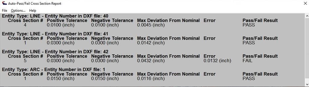
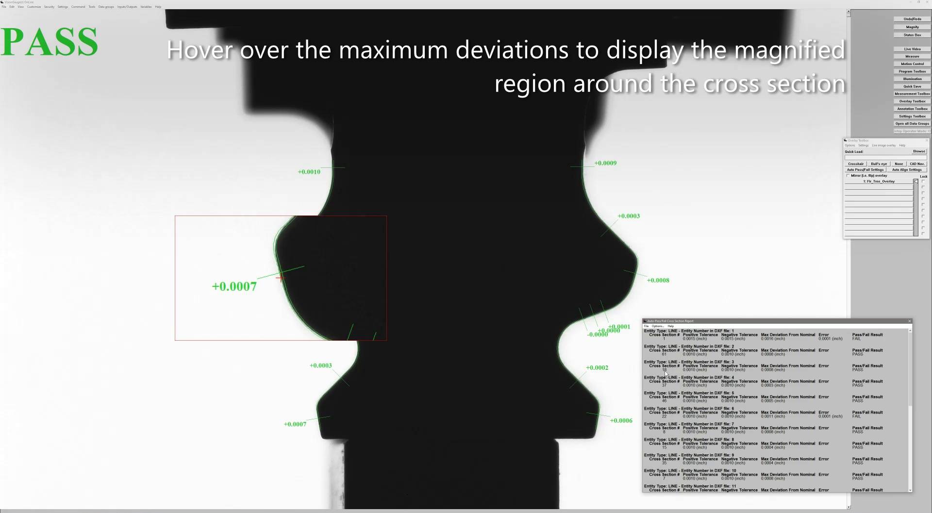
Auto-Pass/Fail Cross Section Reports can be filtered to display only the cross section with the maximum deviation from nominal per entity – displaying quickly where a part failed.
Auto-Pass/Fail Cross Section Reports can be filtered to display only the cross section with the maximum deviation from nominal per entity – displaying quickly where a part failed.
VisionGauge’s CAD Auto-Pass/Fail Cross Section Analysis mode permits operators to quickly scan and review out-of-tolerance areas of a part following an Auto-Align.
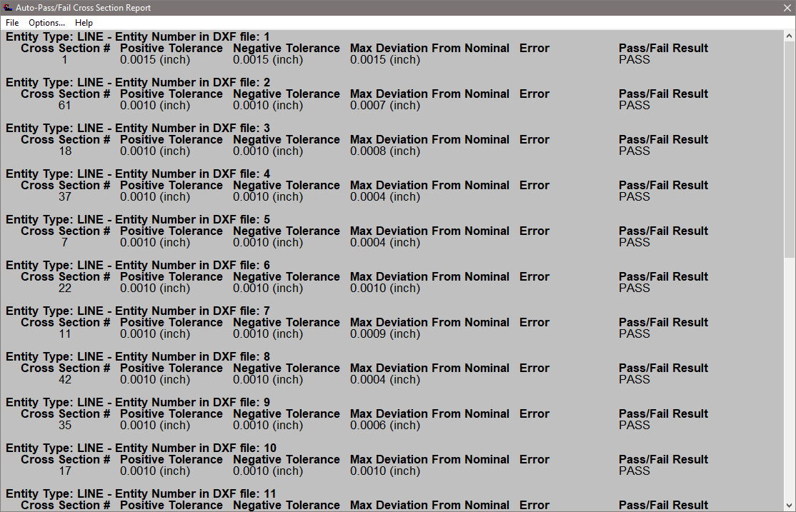
A CAD Auto-Pass/Fail Entity Cross Section Report can apply filters to display a streamlined report, including the maximum deviation per entity. This allows operators to quickly determine which sections may have Failed results and by how much.
The results of CAD Auto-Pass/Fail displayed as an Entity Cross Section Report for inspection of a firtree. Operators are able to hover over a cross section result to highlight and magnify the region of interest on the image.
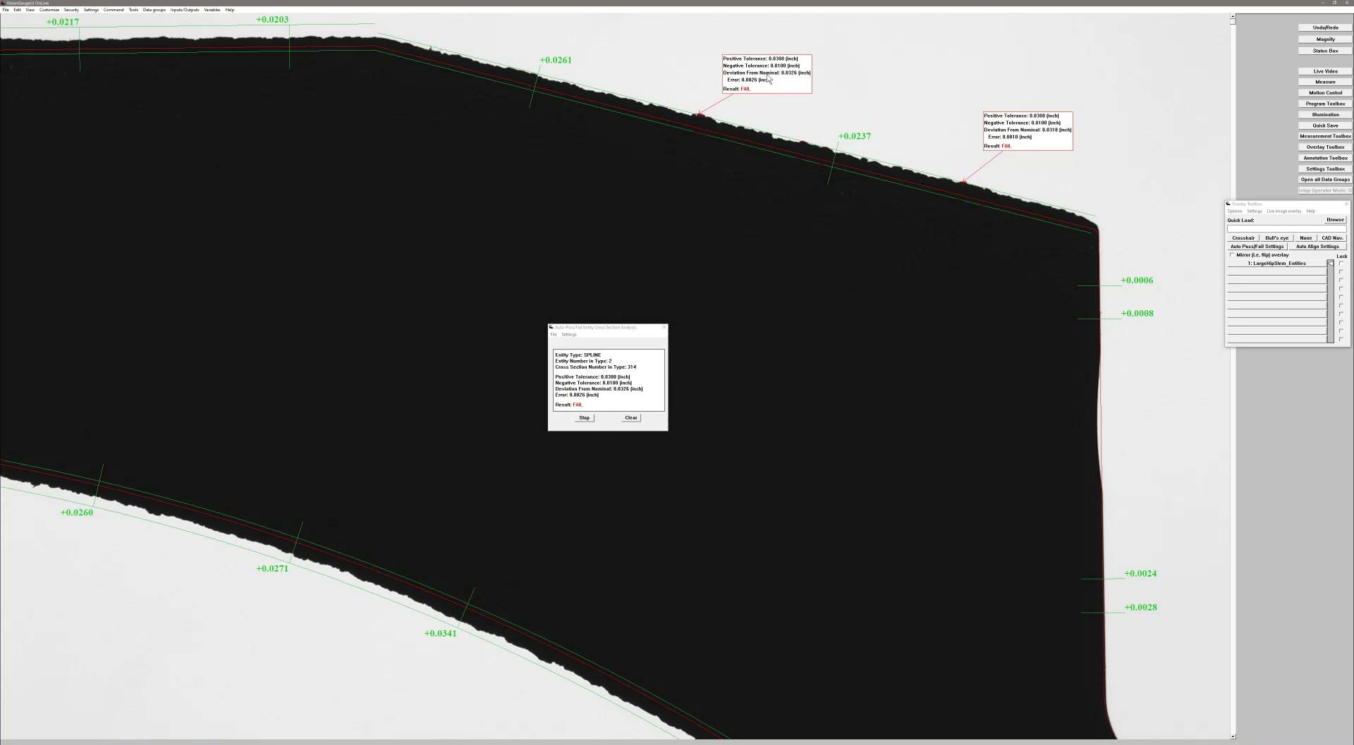
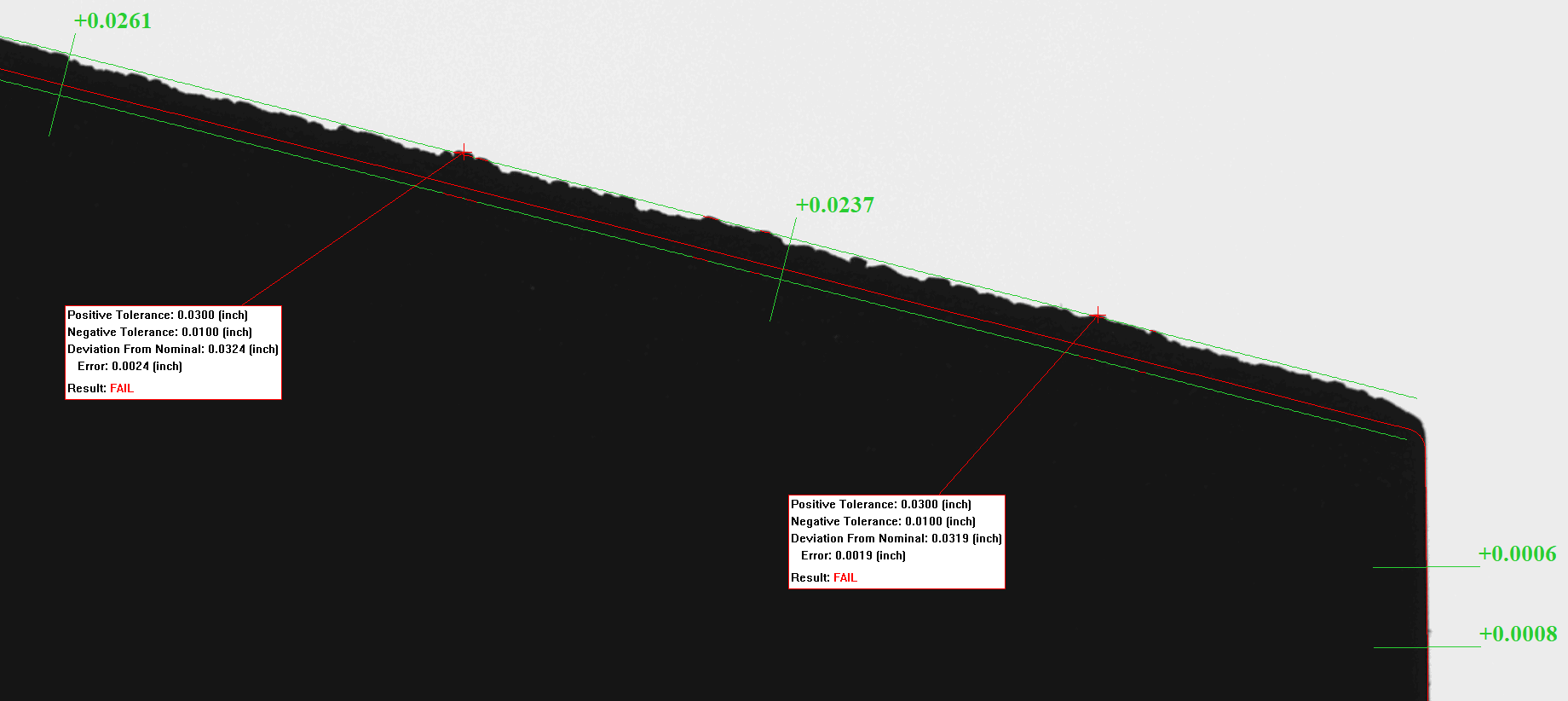
CAD Auto-Pass/Fail Entity Cross Section Analysis allows operators to quickly and easily interact with the results of an inspection. By hovering the cursor over the Auto-Aligned edges of the part, the operator can view the results of the CAD Auto-Pass/Fail tool at each cross section. Annotations can be made directly on the image to include in inspection reports and highlight problem areas.
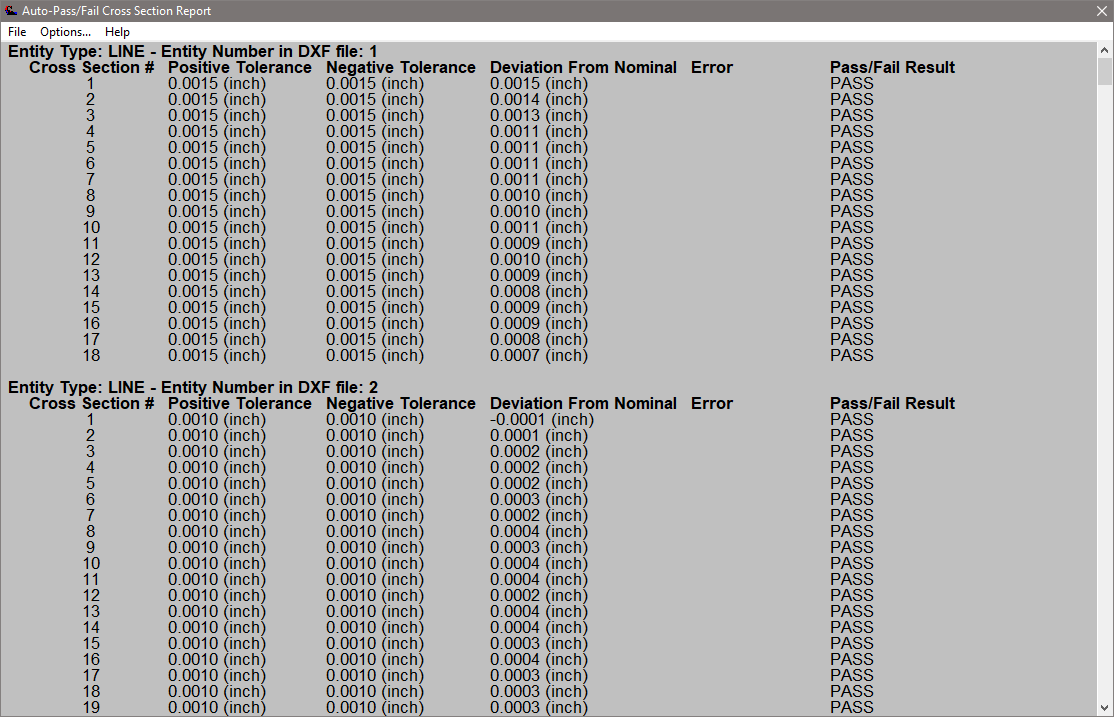
VisionGauge’s CAD Auto-Pass/Fail Entity Cross Section Analysis permits operators to view a report on the results of the Auto-Aligned part in the field-of-view. Filters can be applied to the report to display only those results of interest. Hover the cursor over report entries to magnify the inspection region at that cross section and display the edge located during the CAD Auto-Pass/Fail operation.
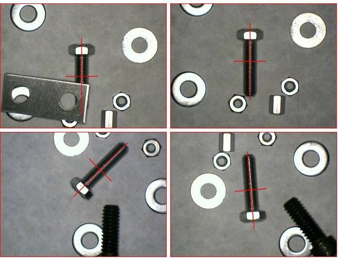
example images of VisionGauge’s pattern matching tools identifying a feature in various orientations and with partial occlusion.
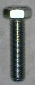
The pattern matching pattern provides the template against which pattern matching searches are compared. This should be the ideal part/feature for the application under the ideal circumstances (illumination, placement, etc.)
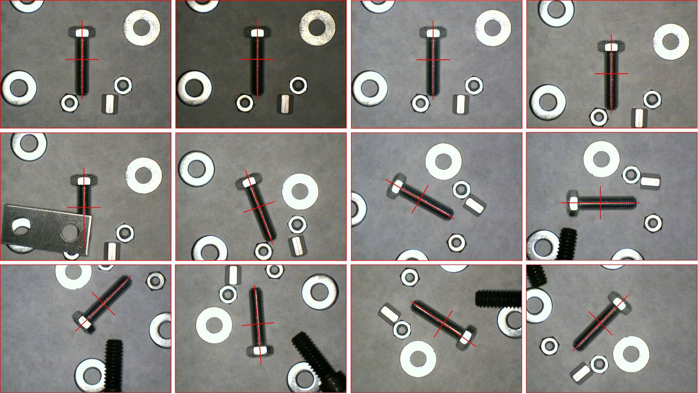
VisionGauge®’s powerful pattern matching tools are adapted to solve a wide range of applications to identify and accurately locate objects in images and features on objects. These robust pattern matching tools are adapted for arbitrary objects & features in any orientation, can handle partial occlusion and hold up to partial deformation, and deal well with variations in illumination and noise.

VisionGauge OnLine can handle locating the edge break of rounded edges completely automatically with high-accuracy.