Specifying Tolerances for VisionGauge®’s Patented CAD Auto-Align™ & CAD Auto-Pass/Fail™ Tools
VisionGauge® offers two ways to specify tolerances. The first is to simply enter them directly in the VisionGauge® software. VisionGauge® has a simple and intuitive interface to allow you to do this quickly and easily. It is extremely flexible and supports the common bilateral “plus / minus” tolerances as well as “plus / plus” and “minus / minus” tolerances. Furthermore, VisionGauge® allows you to specify both uniform and linearly variable tolerances. All parameters can be set on an entity-by-entity basis and VisionGauge®’s “snap to entity” tool makes it easy – even in very busy drawings - to quickly set everything up.
VisionGauge® can also read in tolerances directly from CAD files. In this case, the tolerances can vary arbitrarily, i.e. uniform, linearly or otherwise... This is the absolute fastest way to setup CAD Auto-Align™ and CAD Auto-Pass/Fail™ operations. Everything can be setup in under a minute, with time to spare.
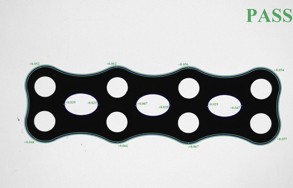
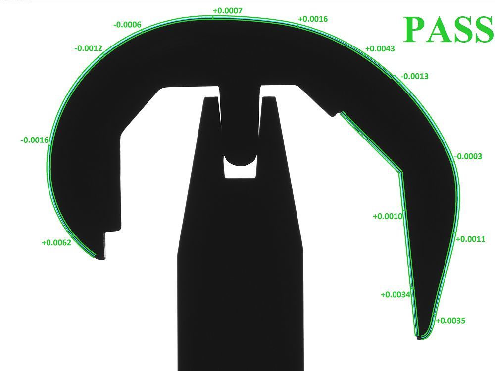
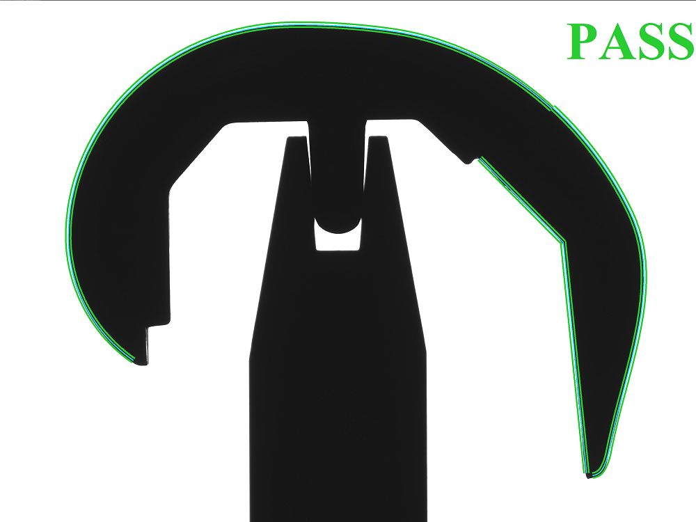
In both cases, VisionGauge® offers a wide range of display options, including the following:
- hiding the nominal (to avoid clutter)
- displaying the maximum deviation from nominal over either all or certain user-specified entities
- displaying the search range
- a wide range of line styles and colors as well as unique display modes
- etc...


