VisionGauge® OnLine version 16.51 is available for download

VisionGauge® OnLine version 16.51, dated August 19th, 2024, is available for download.


The following new features and enhancements have been added over the past several versions:

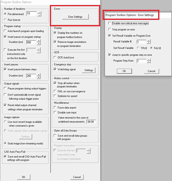
Program Toolbox – Error Options

The Program Toolbox now contains new Error Options in the Options setup, with the ability to set variables on error or jump to specific steps on error.

Absolute Value of Deviation from Nominal

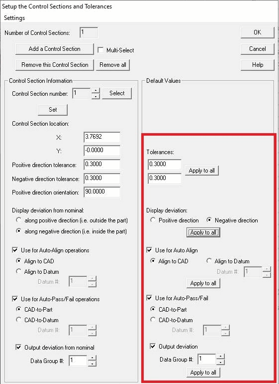
We have added the ability to output the absolute value of the control sections’ deviations from nominal to a Data Group. This also modifies the tolerances accordingly, when applicable. The new option to output the absolute value is defined when setting up each control section. Note that the displayed deviation from nominal on the image will still be the actual value as computed, and only the value output to the Data Group will be modified.
This update further enhances the robustness of the Threads measurements ROI selection. To be able to carry out proper measurements with the pitch, the minimum required number of full thread crests and roots is now 2.

This update also adds support for horizontal thread measurements (for vertically position screws), including all the previous measurement capabilities for threads. The orientation of the threads is selected in both the manual measurement mode and the Program Toolbox Measurement step in the the Threads Measurement tab.

A new “Print” option has been added to Data Groups under the “File” menu to allow printing the currently shown data in the Data Group (across multiple pages, as needed).

In this update, additional support has been added when setting up computer controlled illumination to skip over/offset a module’s channel. This permits our technicians to setup the new octant-based illumination with other illumination channels in a more familiar configuration, with backlight set as the first channel.

On systems with DirectX compliant video acquisition devices, when opening the “Settings – DirectX Video Properties” menu to adjust camera settings, live video will now activate to display live feedback of the changes being made.

Improved Counting and Sizing operations when using dilation adjustments to ‘merge’ close objects.

Addition of a “Smallest Object Equivalent Diameter” measurement with tolerances for Counting and Sizing operations.

Counting and Sizing “Largest object..” results now factor in user limits when returning the largest object in the ROI.

VisionGauge OnLine’s DDE Server capabilities have been updated with the following topics:

A new “Quicksave” Topic was added to our DDE server support to activate the QuickSave feature with its current configuration (in the Settings – General Preferences). When the image has been saved, the filepath is returned to the DDE client.

Also a new “Measure” Topic was added to start a measurement and return the result from the DDE client (e.g. Excel). The Item string serves as a description of the measurement being taken.

Ethernet Motion Control Drive support:

Improved timeout scenarios when awaiting a response from an ethernet motor drive before disabling the drive.


Multilingual/Localisation Support:

This updates adds further multilingual support. The following windows have been updated with localisation support:

Annotation Label for measurements
Configure Measurement Toolbox Label
Allow User to Confirm Measurement
Area/Pathline Measurement windows
Measurement Additional Settings window
Measurement Toolbox + Set dialogs
Snap Mode window
Units dialog + Advanced
String/Numerical Variables Setup

Support has been added for Unicode characters in Automatic DDE to Excel filepaths and in the Program Toolbox “Step” label.

All String Variables can now be Unicode strings.

This update adds the ability to bypass requiring a password for operators when accessing the Live Image Overlay Settings menu, if the Security Manager has been setup with password protection. This grants operators access to specific overlay settings. However, further access to DXF Overlay calibration and alignment-specific settings are still password protected.

The following fixes have also been made:

  • This update corrects an issue in the Program Toolbox where ROI’s for the Threads or Trace Width measurement tools may need to be reset when loading programs with previously saved ROI’S.
  • Fixed an issue in Remote Program Communications when receiving multiple commands at once that may contain errors or that may repeat the same command. Previously commands received simultaneously during the same input window would only execute the first command.
  • An issue was also fixed that may cause a crash during Digital Input Monitoring or Remote Program Communications if a program was running in the Program Toolbox but the toolbox itself was closed.
  • This update includes a fix that can prevent a designated program channel from properly saving the selected program in the Input Monitoring window.
  • Fixed an issue that might occur when shutting down VisionGauge OnLine that could crash the software if the Status Box is in a certain state.
  • A potential crash has been fixed when opening the Measurement Mode window when a Marker to Marker tab is already active, or when changing to the the Marker to Marker tab on some systems due to Datum/Lines data being selected and updating.
  • This update includes a fix for a crash that can occur when opening the CAD Navigator window multiple times in a row.
  • This update adds improved handling for warning/error notifications, particularly when errors are reported from various threads, preventing crashing in various cases – mostly relating to live video display. This improves stability of the software in the event of various errors which could present as random software crashes.
  • This update fixes a bug when inserting or deleting Program Toolbox steps where some parameters in Data File steps later in the program than this insertion/deletion point would not transfer to the new step position.

VisionGauge® OnLine version 16.16 is available for download

VisionGauge® OnLine version 16.16, dated December 13th, 2023, is available for download.


The following new features and enhancements have been added over the past several versions:

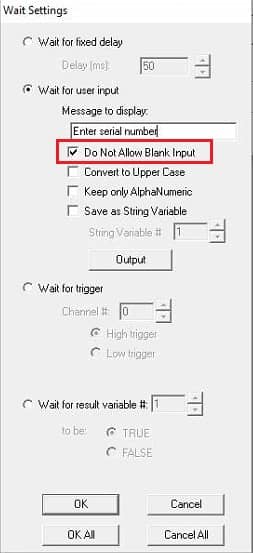
Program Toolbox – “Wait” Settings

The Wait Program Toolbox step has been updated with a new option that would disallow empty input from a Wait – “Wait for user input” step. When selected, the dialog prompt to enter input will continue to be displayed until non-blank input is entered.

Program Toolbox - updated Waitstep options

Parallelism and Perpendicularity Alternate Mode

An option for an alternative method to measure Parallelism and Perpendicularity has been introduced when performing these measurements either manually or through the Program Toolbox. This alternate method specifies the first two points to define the initial reference line, as before. However, the third point establishes a single point on the comparison line, while the 4th point establishes a direction for the comparison line to extend. An extra parameter is required to specify how far away on the comparison line to project the point to be measured. The returned measurement is the projected point to the 2nd reference line (still defined as a line parallel to the 1st reference line passing through the 3rd point).
A new “Additional Setup” dialog allows enabling this alternate method during measurement selection.

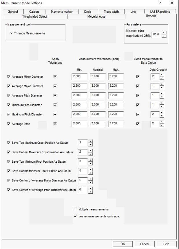
We have added support for new Thread measurement and inspection tools in the manual and automated measurement modes. When selected, this measurement mode allows multiple measurements to be returned from the result of drawing a single ROI around the top and bottom threads. A minimum of 4 threads is required to complete all measurement options.

Thread feature measurements currently able to be reported include:

  • Average minor diameter
  • Average major diameter
  • Average pitch diameter
  • Minimum pitch diameter
  • Maximum pitch diameter
  • Average pitch

Thread Inspection setup dialog

Specific points calculated from the measurements can also be saved as Datums for re-use in further measurements.

For more information and an overview video, visit the Thread inspection and measurement page.


The top-bottom thread edge profile detection has been improved with regards to filtering stray contaminants above/below threads.

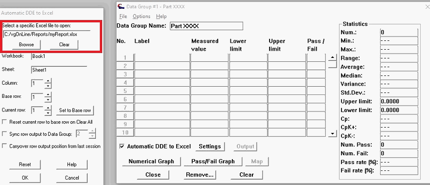
This update introduces template Excel files that are used to automatically create specific Excel files when outputting data from the Data Groups, without having to pre-create the target Excel file. Currently supported templates are Excel files with the extensions .xlsx, .xls, .xlsm.
The new, blank template files provided in the C:/vgOnLine/Reports/Templates directory can also be customized, or replaced with your own standard templates in this directory renamed the target extension as ‘template’.

Automatic Export to Excel from VisionGauge OnLine


Writing Data Groups to file with string variables used into the filename will now replace the ‘:’ populated by a date/time string with dashes, for Windows file naming compatibility.

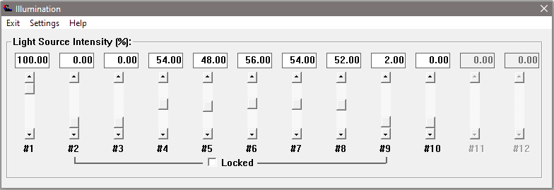
We have added support for up to 12 light sources in VisionGauge® OnLine, including the ability to ‘lock’ sequential channels together so their illumination levels all increase/decrease together. Locked illumination channels can be unlocked to control the channels individually. This can be useful for fine illumination control with specific modules that have multiple LEDs.

The software interface for VisionGauge’s® octant-based illumination is intuitive, extremely flexible and fully programmable.

This update supports our newly released Octant-based Reflected Illumination module.


We have also enhanced general performance for manually controlling computer controlled illumination channels to reduce lag when adjusting the values.

The log file has been updated to include Program Toolbox steps as well as status box messages when enabled.


A camera rotation configuration has been added to the Image Capture Settings. This configuration is useful in specific system builds and camera selections when it fits the application.


We have added expanded support to read analog input with new devices. These new devices also have the option during configuration to convert the analog input result to voltage.

  • We’ve carried various performance enhancements and user interface quality improvements.

The following fixes have also been made:

  • Fixed various potential crash conditions when executing and loading programs
  • Outputting data as whole numbers to a Data Group that has existing real values may temporarily modify the number of significant digits of the entire Data Group. This has been resolved.
  • Fixed a crash condition when reading in overlays after an overlay with Tooth Checker settings enabled has been read in.
  • Fixed an issue when the first instance of displaying live video in some scenarios may result in the software appearing to freeze up.

VisionGauge® OnLine version 15.88 is available for download / VisionGauge® version 11.26

VisionGauge® OnLine version 15.88, dated July 14th, 2023, is available for download.


The following new features and enhancements have been added over the past several versions:

Program Toolbox – “Pause” Settings

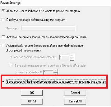
A new option has been added to the “Program Toolbox – Pause” step settings to allow saving the current image in the program before pausing and restoring that image when the program resumes. This option is enabled by default. Disabling this option would use the current image at the time the program is resumed (if the image changes while the image is paused…)

Program Toolbox - updated Pause step options

Program Toolbox – Image Overlay Settings

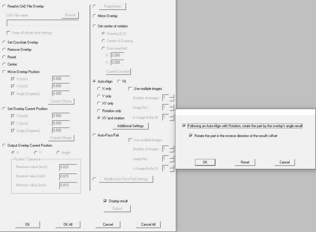
Additional Settings have been added to the “Program Toolbox – Image Overlay” step for an Auto-Align operation. These settings only apply to certain systems that have been setup with axes for part rotation. In this configuration, users can now choose to follow-up an Auto-Align step by rotating the axis controlling part rotation by the amount of the offset of the Auto-Align step result.

Image Overlay - Auto-Align Part Rotation Settings


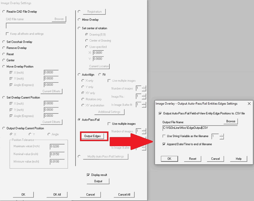
We have also added an option in the “Program Toolbox – Image Overlay” step to allow output to CSV file of the X,Y position of the located edges from the Auto-Pass/Fail operation on Entity cross sections. All Entity cross section edges located in the current field-of-view are output to the CSV file. The output file name is able to be configured by the user manually or by using a stored string variable. It is also possible to add a time/date string to the end of the filename at the time of output.

Image Overlay - Auto-Pass/Fail Settings - Output CSV file

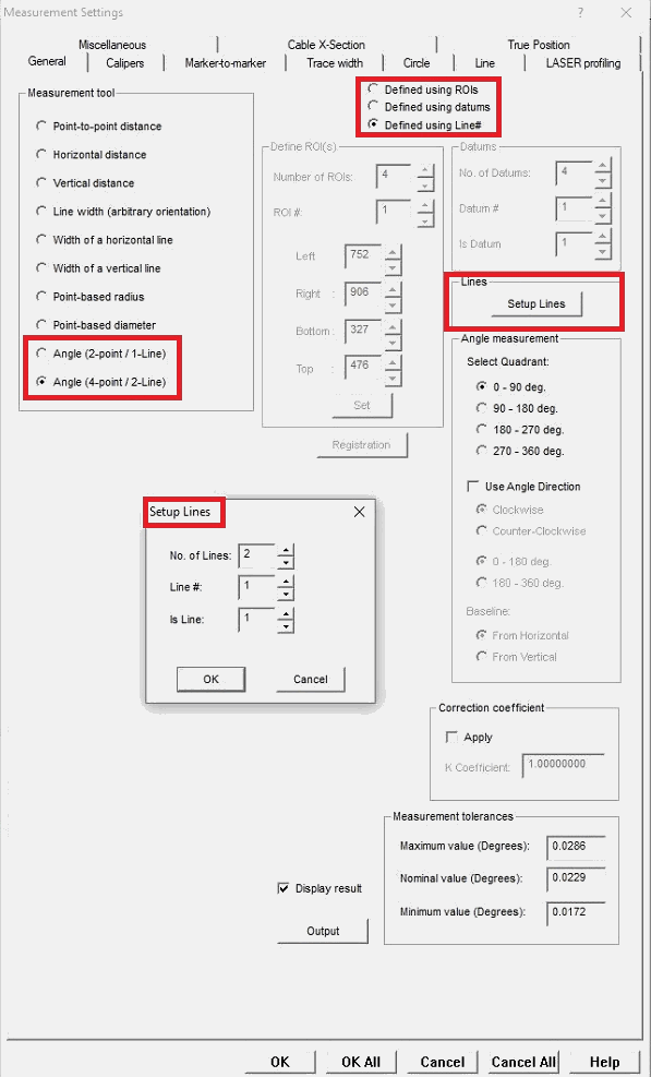
Expanded support for defining measurements using Line datums

We have expanded support for Line measurements in manual and automated measurements in the latest version of VisionGauge® OnLine. These enhancements allow operators to use the “Line Finder” and “Edge Break” measurement tools to save a located line as a Line datum (similar to our Datums), and then re-use these “Lines” in future measurements. As with Datums, these Lines travel with a part as the stage moves, such that a Line defined on the edge of a part still references the same edge as the part moves along the stage. For some measurements, previously only a single Line was able to be defined for measurements, and now we allow multiple lines to be defined to support more complex measurements.

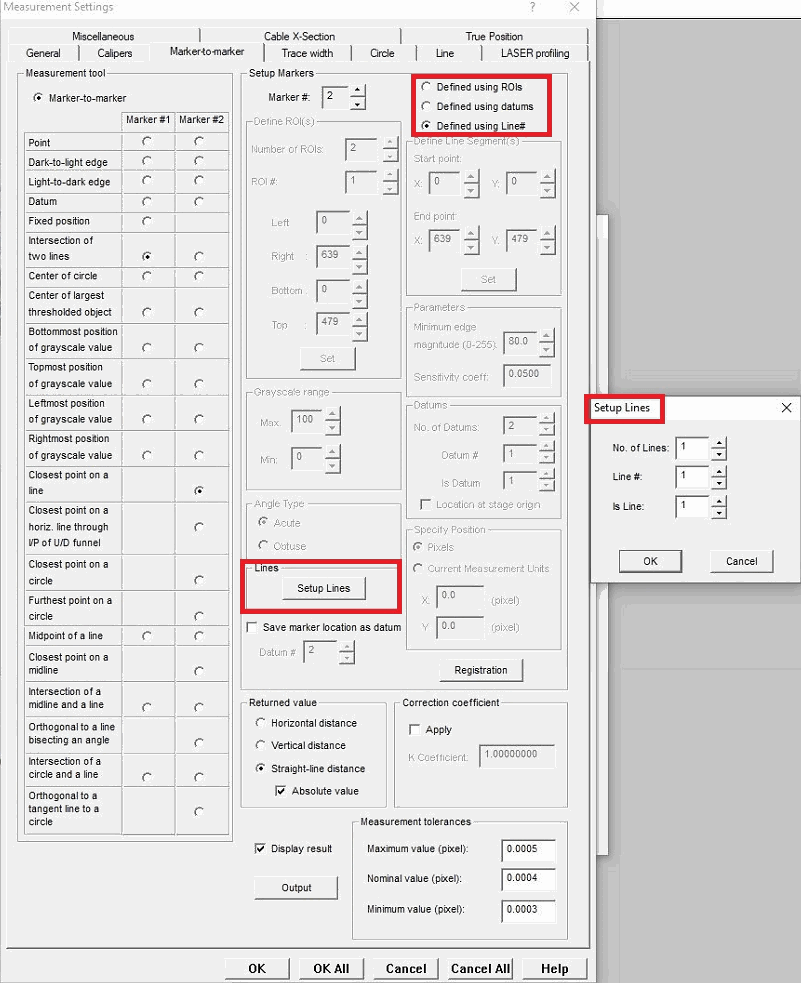
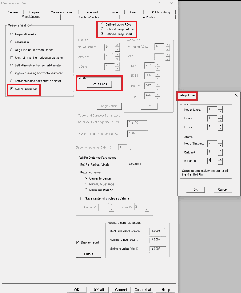
Setup of these measurements can now select Define Using Lines to enable options to define which Lines to use. Measurements supporting definition using these Line datums include:


General Measurements:

  • 2-point” angles measuring from horizontal or vertical – requiring 1 Line
  • “4-point” angles measuring between two lines – requiring 2 Lines
General Measurement Modes Defined Using Lines


Marker-to-Marker Measurements:

  • Intersection of 2 Lines – requiring 2 Lines
  • Orthogonal to a Line (or Closest Point on a Line) – requiring 1 Line
  • Orthogonal to a Line Bisecting an Angle – requiring 2 Lines. This measurement can now also be defined with standard Datums, too.
Marker to Marker Measurement Modes Defined Using Lines


Miscellaneous Measurements:

  • Roll Pin Distance – requiring 4 Lines (2 Lines per Roll Pin). An additional point is required to select approximately the center of each of the Roll Pins and determine between which line segments the Roll Pin is located: In a manual measurement, the operator must use the mouse to select where the Roll Pin is located, while in an automated measurement, a Datum must be defined before that is located in the appropriate segment.
Miscellaneous Measurement Modes Defined Using Lines


We have also included an option when using the Line Finder and Edge Break tools to apply iterative sub-pixel refinement which can greatly improve the resulting Line along imperfect edges.

Iterative sub-pixel refinement for Line detection.

Intersection of a Circle and a Line Projection & Orthogonal to a Line Tangent to a Circle Measurements

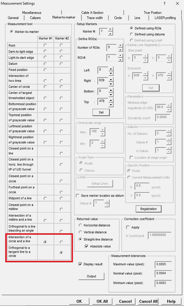
This update adds 2 more automated measurements to the Program Toolbox – Measurement step. The Marker-to-Marker measurements now include “Intersection of a Circle and a Line Projection” and “Orthogonal to a Line Tangent to a Circle”, which were previously introduced to the manual measurement mode.

Marker to Marker new automated measurements April 2023

RS-232 COM Measurement Device Support Added

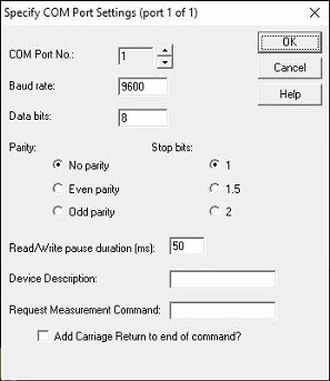
Support has been added to allow measurements from RS-232/COM devices (or those with USB adapters that create a COM port in Windows). When starting VisionGauge® OnLine with this update, the user will be prompted if they want to support any of these devices.

RS232 measurement device configuration

During configuration, the RS232/COM device parameters must be entered for each device, including bit rate, data bits, parity, stop bits, a device description, and the command to request a measurement from the device.

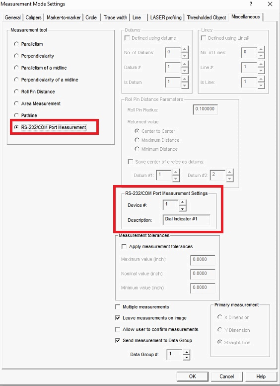
A new option for RS-232/COM Port Measurement has been added to the “Miscellaneous” tab of the manual measurement mode, as well as the Program Toolbox – Measurement step. During this setup, users need only select the number of the device they setup.

RS232 measurement device setup

During manual measurement mode, simply pressing the Measure button will obtain the reading from the device and send it to a Data Group accordingly.


Roll Pin Distance Returned Value update

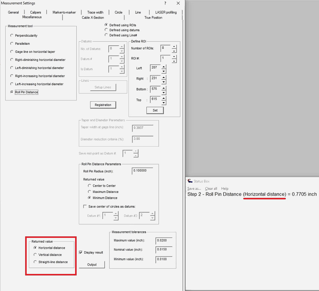
We have added a “Returned Value” option in the Program Toolbox for “Roll Pin Distance” measurements. As with other measurements that support it, this permits the user to determine if the straight-line distance is returned between the measurement points or only the horizontal or vertical component of this distance.

Roll Pin Distance Returned Value update

We have also added clarification to the measurement string returned about which value is selected. The same adjustments have been made to the manual measurement mode for Roll Pin Distance, referred to as “Primary Measurement”.

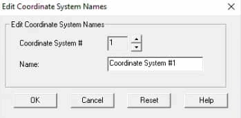
We have added the ability to edit the Motion Control Toolbox’s list of System Coordinate names. By default these are named “Coordinate System #X” for each label, up to 20 coordinate systems. At the bottom of the System Coordinate menu, users can now access a dialog box to edit these names. The names will carryover from session to session of the software.

Edit system coordinate names in the Motion Control Toolbox

We have enhanced the software to accommodate recent hardware changes to our newer ethernet motion control drives. Existing system with drives in this configuration will remain unchanged, except the software will startup faster than before.


We have added a 1-second wait after a stage has been instructed to home to allow the motion control system to settle after the last movement before setting the position to zero for greater positional accuracy when applying 2D XY Stage Corrections.

To protect against lost software settings when Windows is shutdown or restarted while VisionGauge® OnLine is still running, VisionGauge® OnLine will now signal that it is still running and object to shutting down Windows before the software is properly closed. If a Windows shutdown event forces VisionGauge® OnLine to close without saving the current settings, the user will be notified about the event upon startup of the following session and the last properly saved settings will attempt to be used. Examples of such shutdown events are Windows automatic updates, users logging off, and other manual or automatic restarts. As a reminder, it is highly recommended to shut down VisionGauge® OnLine properly before initiating a Windows reboot, shutdown, or user log-off operation.


We have added a notification for users when attempting to read in a newer version of Control Section or Entity-Based Auto-Pass/Fail files. The same notification is also now available for setup files. This may prevent certain crashes users experience when reading in unsupported files, particularly when sharing files between systems that do not have the same software revision.


We have expanded support for input/output of rotary stage coordinates in the Degree/Minutes/Seconds format. These units can be selected as usual from the “Settings – Units” menu. Various locations in the Motion Control Toolbox, Program Toolbox, and output have been updated with this support.

  • We’ve carried various performance enhancements and user interface quality improvements.

The following fixes have also been made:

  • We have corrected an issue where the manual measurement mode could be switched during an active measurement operation, which could cause a software crash with certain measurement types.
  • We have corrected an issue where the software used the wrong value when outputting the overlay’s rotation position to a Data Group from the “Program Toolbox – Image Overlay” step.
  • We have corrected an issue when recalling an overlay through a Data Group may change the units to ‘pixels’ if images are being collected in the Data Group. Also recalling an overlay through a Data Group previous might not have properly displayed edge search ranges for Auto-Pass/Fail entities.
  • We’ve corrected an issue where certain .dxf files may appear to read properly, but would display no entities or only text entities overlapping each other.
  • We’ve corrected an issue that may happen intermittently when manually starting an Auto-Align operation in the Overlay Translation/Rotation window. In those instances, the Auto-Align may appear to start but finishes immediately without actually moving the overlay: Pressing the button additional times results in the Auto-Align operation starting and completing as intended. This has been resolved and operates as intended on the first button press.
  • Previously Data Groups that had the option to restore overlays and offsets enabled were unable to properly restore the overlay when a result was populated by an automated program. This has been resolved and overlays are restore no matter how the result was populated.

VisionGauge® version 11.62, dated June 21st, 2023, is available for download.


The following new features and enhancements have been added over the past several versions:

  • We have corrected an issue where the manual measurement mode could be switched during an active measurement operation, which could cause a software crash with certain measurement types.
  • Support has been added for a USB version of the encoder/decoder board used by the Manual and Motorized Stage versions of the software, to replace the PCI version.

Automation in Manufacturing

It’s no surprise that the global industrial automation market is expected to reach $430.9 billion by 2030. Automation is an increasingly popular engineering feat for more efficient labor, time and cost savings, increased safety protocols, and often better products overall. Discover the benefits of automation systems in various manufacturing industries.

What Is Automation in Manufacturing?

Manufacturing automation uses specialized equipment to streamline production assignments, systems, and processes. It’s incredibly helpful for repetitive tasks or those requiring high precision.

Manufacturing processes like assembling, inventory management, handling, processing, and quality inspection can all integrate automated technology. Automation in manufacturing aims to elevate capacity, lower operating costs, improve productivity, and enhance workplace safety measures.

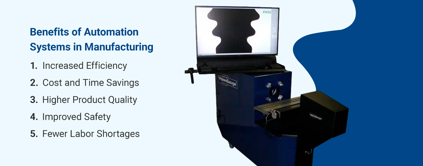
Benefits of Automation Systems in Manufacturing

Below are some advantages automation can provide for manufacturing.

1. Increased Efficiency

Automated machines can work unattended 24/7, maintaining the same speed and efficiency throughout. Advanced equipment, robotics, and sensors can oversee inventory, system maintenance, and quality checks on completed products. They can seamlessly disperse this data throughout the supply chain. This maximizes scheduling and planning, decision-making, and return on investment (ROI).

Automation can help your operations persist longer and boost productivity. You can generate new or more products without disrupting manufacturing. Additionally, this increased production speed gives companies higher responsiveness to market fluctuations, helping them stay ahead of competitors.

2. Cost and Time Savings

Many machines can perform the work of several people at a time with fewer defects, offering significant value and cost savings in the long run. Automated technology can also generate more products and complete inspections in less time. This increased production rate saves considerable amounts of valuable time.

3. Higher Product Quality

Machines can typically complete manufacturing processes with greater accuracy than human employees, all while ensuring the same product quality throughout. This allows for a lower error rate and overall better products. Standards can be stricter and products more competitive in the market.

4. Improved Safety

In 2022, the Occupational Safety and Health Administration (OSHA) cited over 22,000 U.S. workplace safety violations among its leading complaints, including citations in fall protection, hazard communication, respiratory protection, and other areas.

Reducing human error with automation can create a safer workplace, as it reduces repairs, recalls, and potentially severe injuries. Before advanced machinery, many manufacturing processes required employees to work for extended periods around various hazards, such as chemicals, electricity, machine guarding, equipment maintenance, and more.

Generally speaking, incidents like machine malfunctions and slipping or tripping on loose materials can be prevented with this technology. Automation helps keep workers away from dangerous substances or processes.

5. Fewer Labor Shortages

Automated machines can combat labor shortages and their resulting effects, as they’re less likely to be in low supply than human workers. Sufficient labor makes all the difference in a manufacturing company’s success.

Top Industries to Benefit From Inspection Automation

Automation is revolutionizing many industries, from retail and transportation to electronics. Below are merely a few of many industries that benefit from automated processes.

1. Aerospace

Given the immense size and scale associated with aircraft, the aerospace industry faces complex manufacturing requirements. Large components often require human operators and robots to work in tandem. In many cases, mobile robots that can travel between large aircraft parts are necessary to facilitate the process.

Moreover, robots can work in tight, hard-to-reach spaces, further enhancing productivity and quality. Automation minimizes the need for aerospace engineers to perform repetitive tasks, manipulate heavy objects, squeeze into tight spaces, and perform other hazardous processes while still adhering to critical quality standards.

Airplanes components have numerous holes that require drilling. Using special vision technology, robots can accelerate this drilling process while improving accuracy. Additionally, robots can assist and perform a wide variety of other tasks in assembling, preparing, inspecting and testing aircraft parts and components.

2. Medical Manufacturing

Given automation can perform tasks with fewer errors and higher precision, it’s an excellent tool for manufacturing, reporting, and documentation of medical devices and pharmaceutical products.

Automated medical device and implant manufacturing enhances quality control, assurance, and consistency. Using complex computing technology, cameras, and sensors, it provides accurate inspections, error detections, and automatic corrections. It also outputs and stores results for future reference, benefiting subsequent medical production processes and documentation for audits to maintain the highest industry standards.

While manual production requires constant slow-downs and stops for human evaluation, automation performs at high speeds, instantly detecting if a device is out of tolerance.

3. Automotive

In the automotive industry, robotics can lower human error in processes requiring automated reporting, manufacturing, and documentation. Their programmed safety features stop machinery when a worker gets too close, preventing a potentially serious accident.

Most automotive manufacturers use some form of automation at nearly every vehicle production stage. Tools like machine vision and robotics can perform a variety of tasks like welding, testing, inspection, and assembly. Automation improves safety, quality, and productivity in the automotive industry, completing more tasks in less time with minimal inaccuracies.

4. Packaging

Automation is a great way to increase packaging capacity. Robotic arms, for instance, are ideal for packaging applications due to their freedom of movement, high payload capacity, and ability to complete labor-intensive tasks in less time.

Manufacturers in the packaging industry can leverage technology to maintain a competitive advantage, product consistency, worker safety, and packaging flexibility for larger and more complex product varieties.

Best Automation Equipment and Systems

Various automation solutions can simplify different processes and tasks for manufacturing companies – from complete system automation to assisting certain processes. Some of these technologies include:

  • Machine vision automation: Machine vision technology allows equipment to make quick decisions and verifications based on pre-programmed specifications. It’s ideal for visual inspections, part measuring and positioning, and defect detection. It can also assist in product identification, sorting, and tracking.
  • Optical inspection automation: An optical inspection system can test defects in various parts, for example printed circuit board assemblies (PCBAs). A camera scans the device for scratches, stains, open circuits, shorts, missing components, improperly placed components, and much more.
  • Robot arm automation: Robotic arms manipulate parts and products, which can be used for precise part placement/positioning in further processes, reducing human efforts for repetitive actions and difficult parts, and increasing safety.
  • Robot inspection automation: Visual inspection robots feature complex vision sensors to inspect valuable or critical components, systems, and infrastructure.
  • Cell controller automation/Cell inspection automation: An inspection cell is an enclosed unit or station dedicated to specific inspection tasks for given parts. Cell controllers are devices designed to coordinate, monitor, guide, and report part inspection processes, often linking multiple inspection cells. Through automated cell inspection a part can be accepted in an inspection cell, where an automated system can move around the object or precisely position it for a variety of tasks, including performing measurements, inspection, reporting, etc. The part can then be moved out of the inspection cell for additional processing. This level of manufacturing automation can achieve much higher throughput rates and greater gains in reproducibility, technical precision, and efficiency.

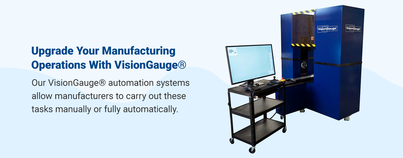
Upgrade Your Manufacturing Operations With VisionGauge®

At VISIONx, Inc., we develop software and equipment for complete visual part inspection, machine vision, image analysis, and defect detection to ensure they meet quality standards. Our VisionGauge® automation systems allow manufacturers to carry out these tasks manually-assisted or fully automatically. We have a wide variety of system types with many customizable options to solve applications across countless industries. Our VisionGauge® Digital Optical Comparator and our versatile Standalone Inspection and Measurement system are perfect to drop into any existing automated application.

These systems can perform various manual or programmed measurements and inspection operations, then collect and output data for streamlined reporting. They can easily interface with external equipment and machinery, such as cell controllers and robots – sending and receiving digital I/O signals or commands over a network. Furthermore, our VisionGauge® systems are incredibly simple to install and run.

If you’d like to invest in our advanced patented technology or learn more about our systems, reach out to our team today.

VisionGauge® OnLine version 15.62 is available for download

VisionGauge® OnLine version 15.62, dated February 7th, 2023, is available for download.


The following new features and enhancements have been added over the past several versions:

Overlay Toolbox Pinned buttons

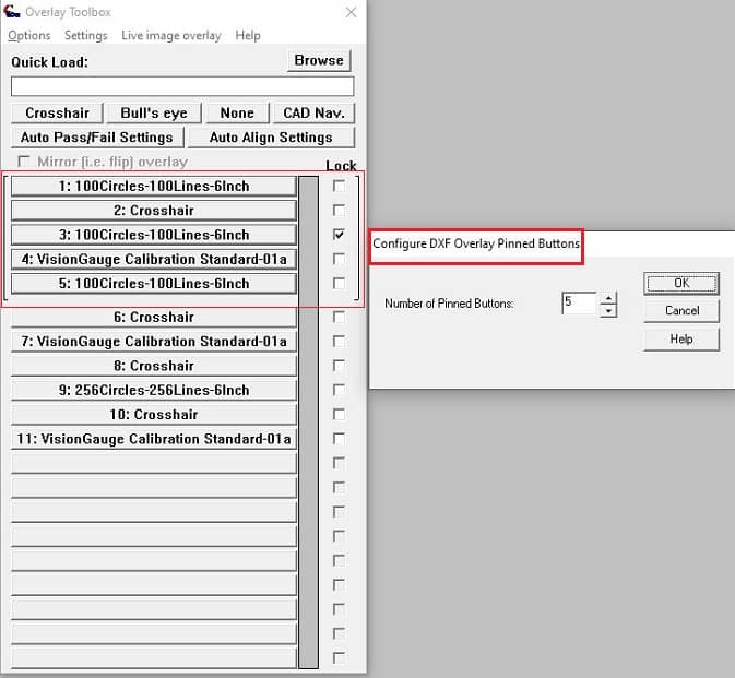
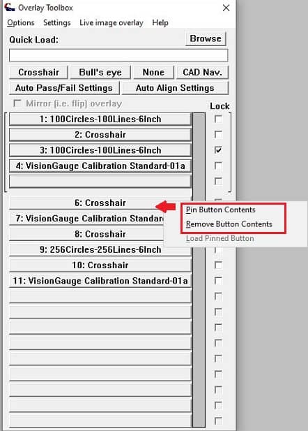
The Overlay Toolbox has been enhanced to allow ‘pinned buttons’ at the top of the list. These pinned buttons will not be cycled down the list of quick recall overlay buttons when reading in a new overlay, and the information loaded into them will persist session after session. These buttons are outlined at the top of the Overlay Toolbox. New overlays loaded through typical actions (Program Toolbox steps, barcode scanning, Overlay Toolbox “Browse” button, etc.) will be loaded into the non-pinned section as usual after these pinned buttons.

Overlay Toolbox Pinned Buttons

A new item in the Overlay Toolbox “Options” menu allows users to configure how many buttons are currently pinned. It is possible to pin the full toolbox set (currently updated to 40 buttons).

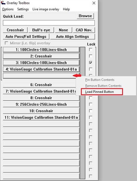
Loading a pinned button is possible by two methods:

You may right-click on the pinned button you want to load and select the “Load Pinned Button” menu option. You can then browse to a file to load as usual.

Loading pinned buttons in the Overlay Toolbox

You may-right-click on an already loaded Overlay Toolbox button and select “Pin Button Contents”, then select to which pinned button number you want to copy this overlay.

Removing buttons in the Overlay Toolbox

It is now also possible to remove the contents of an Overlay Toolbox button by right-clicking the button and selecting “Remove button contents”.

These new options are capable of password protection through the Security Manager. We have also added options in the Operator Mode to disable/enable access to these options.

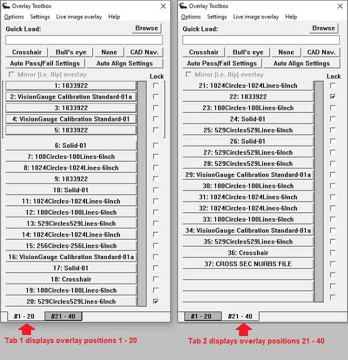
Also, a new “Options” menu item in the Overlay Toolbox allows the user to specify “40 buttons”. When this option is selected, two tabs will appear at the bottom of the Overlay Toolbox. The left tab will display Buttons 1-20 and the right tab will display Buttons 21-40.

Overlay Toolbox - 40 buttons

The last open tab will carryover between sessions of the software. Also the current number of pinned buttons will be taken into consideration across both tabs, allowing for a total of 40 pinned buttons, if required.
Note, loading a new overlay with the Browse option, by the Quick Load, or through the Program Toolbox will add the overlay to the first ‘unpinned’ button, as usual. If the first unpinned button is located on the non-active tab, the tabs will automatically change to display the last opened overlay.

Auto-Pass/Fail Entities Cross Section Analysis/Report

This update adds support for an Analysis and Report mode for Auto-Pass/Fail Entities. This feature works for entities setup either manually or automatically read in from a nominal/minimum/maximum set of DXF files.

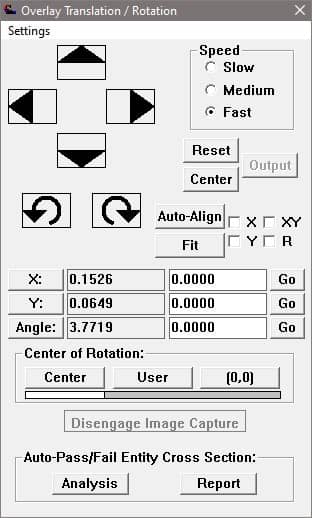
These Auto-Pass/Fail Entity Cross Section Analysis and Report modes are accessible through the Overlay Translation/Rotation dialog when live video is activated with an overlay configured with Auto-Pass/Fail Entities.

Overlay Translation/Rotation Analysis & Report buttons

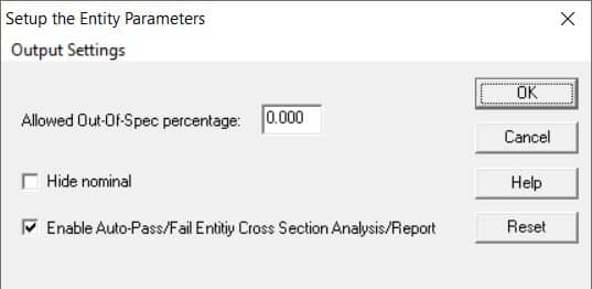
Users may disable/enable access to the Analysis and Report options in “Overlay Toolbox – Auto-Pass/Fail Settings – Entities” section. The option is immediately accessible when loading the Entities settings for a file setup by reading in .dxf files with the minimum and maximum tolerances in addition to the nominal .dxf file. If Auto Pass/Fail Entities have been manually setup on a .dxf file, the option to access these Analysis/Report settings is available in the Entities General Settings menu.

Enable Auto-Pass/Fail Entity Cross Section Analysis/Report


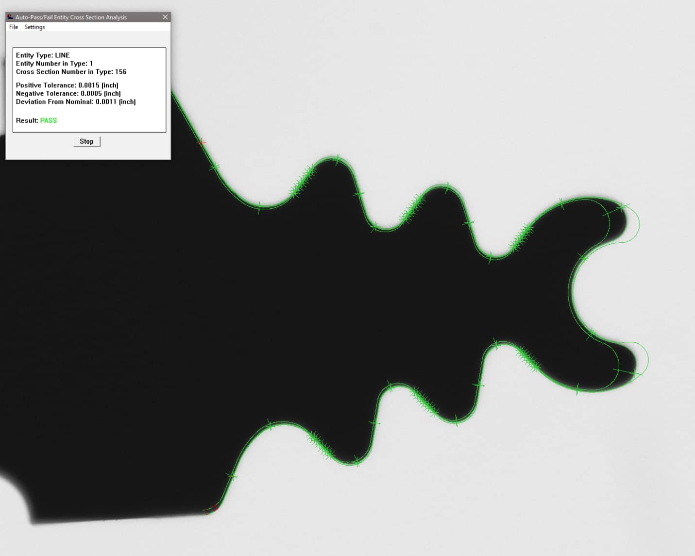
The Analysis mode allows user to inspect and annotate the cross sections along each Entity found in the current field-of-view. A ‘control’ window displays the results of each cross section the mouse cursor is currently highlighting. The mouse cursor will snap to the closest cross section nominal position within a ‘snap radius’ and will also draw a cursor over the edge point located for that cross section, if one was found. Information displayed about each point includes the Pass/Fail result, tolerance information, deviation from nominal, and error from being in tolerance if the result if a Fail.

Auto-Pass/Fail Cross Section Analysis Mode

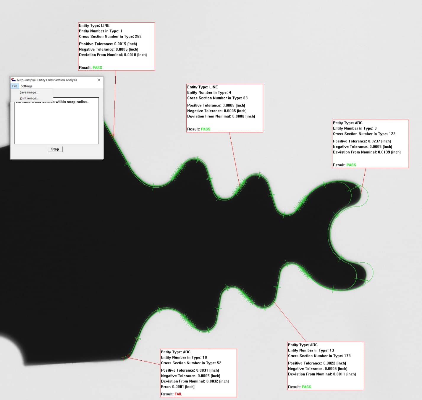
By left-clicking the mouse on the image when a cross section is highlighted, the user will enter an annotation mode where a location can be set for an information box displaying the data for that particular cross section.

Auto Pass/Fail Cross Section Analysis Annotations

The snap radius of the mouse cursor can be adjusted in the Settings menu for this tool. Users may also choose if they want to snap only to Failed result points and configure the data displayed in the annotation box on the image.

When the current “Analysis” has been completed, the user can opt to Save or Print the image by using the “File” menu options.


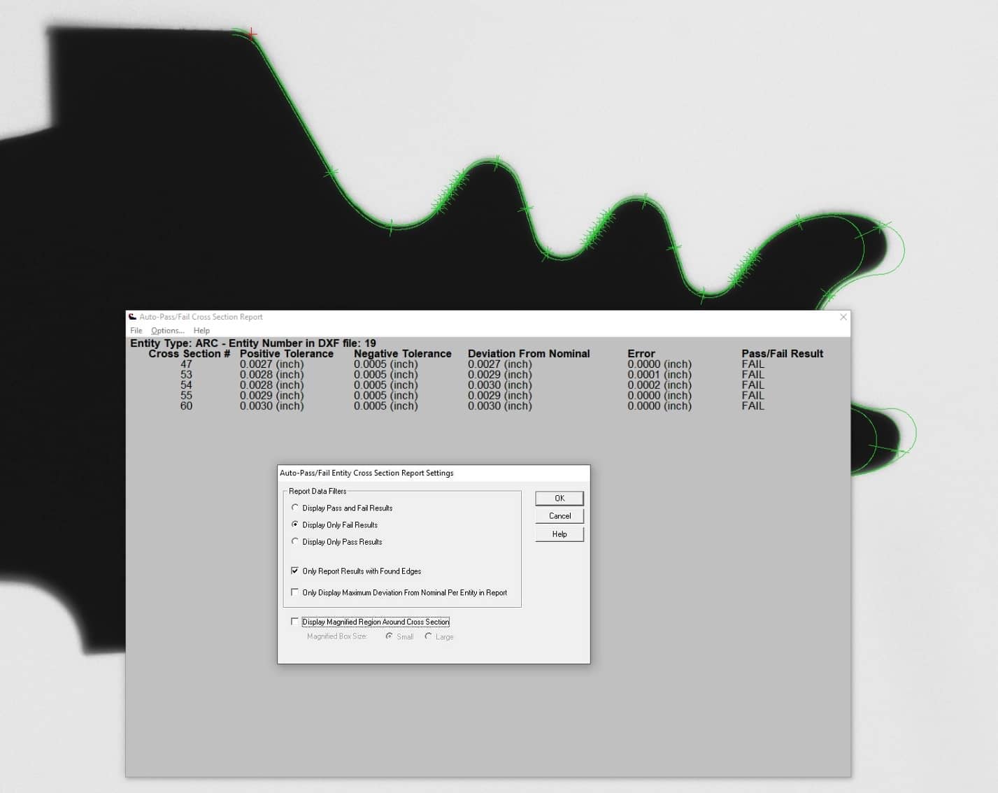
The Report mode displays all cross sections for Auto-Pass/Fail Entities found in the field-of-view in a scrollable report. Hovering over a cross section in the report will display the edge point found, or the nominal point of the cross section if an edge was not found, on the image. An option to display the cross section in a magnified box is enabled by default. The magnification level is controlled by the same settings that control the main window’s “Magnify” operation in the “Settings – General Preferences” menu.

Various data filters in the Report’s “Options” menu allow the user to choose which data is displayed in the report, including options to display all Pass/Fail results, only Pass results, or only Fail results.

CAD Auto Pass/Fail Cross Section Report mode

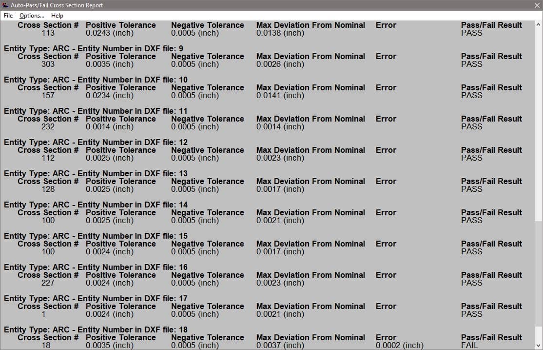
Another data filter provides the option to “only display maximum deviation from nominal per entity in the report”.

Auto Pass/Fail Entity Cross Section Report - Deviation From Nominal only

The report menu also allows writing the edge points found for all cross sections displayed in the current report as either a .CSV file or a .DXF file (with POINT entities).

Auto-Pass/Fail Across Multiple FOV’s in Automated Programs

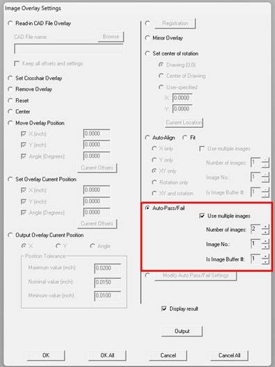
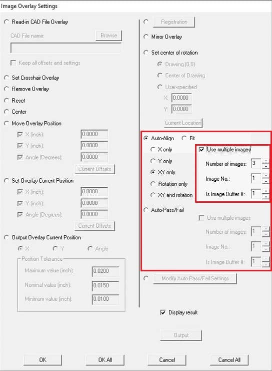
We’ve added support for CAD Auto-Pass/Fail across multiple field-of-view in the Program Toolbox – Image Overlay settings. This feature can now use the multiple image buffers that were previously setup to run these multi-FOV operations and obtain Pass/Fail value across the different FOV’s.

Auto Pass Fail Settings in Program Toolbox

Read more about our enhanced CAD Auto-Align™ beyond the field-of-view.

Auto Pass/Fail Entities – Output Settings

The Auto Pass/Fail Entities feature to Output Settings (Outputting Edge Points) to file has been enhanced with additional columns of data for each edge point.

This report now includes all of the following information:

Nominal X & Y coordinate

Negative direction tolerance band X & Y coordinate

Positive direction tolerance band X & Y coordinate

Edge X & Y coordinate

Deviation from nominal

Pass/Fail

VisionGauge®’s new “CAD Fitting™” tool

The new CAD Auto-Align™ feature “CAD Fitting™” has been added to the Overlay Translation/Rotation window for manual operation and the Program Toolbox – Image Overlay step for automated programs. This alternate mode of the CAD Auto-Align tool can help obtain Pass results in trickier conditions. Learn more about the CAD Fitting™ tool.

CAD Auto-Align™ beyond the field-of-view and depth-of-field

Our enhanced CAD Auto-Align™ capabilities across multiple fields-of-view and depth-of-field have been added to various places in the Program Toolbox. In the Auto Pass/Fail Control Sections Setup for a CAD file, a control section can now be associated with a particular image buffer. Image buffers are also setup in the Program Toolbox – Image Capture step to associate a location with an image buffer. The Program Toolbox – Image Overlay step “Auto-Align/Fit” and “Auto Pass/Fail” operations can now use the multiple image buffers that were previously setup to run these multi-FOV operations.

Program Toolbox Auto-Align Multiple Image Buffers setup

Read more about our enhanced CAD Auto-Align™ beyond the field-of-view.

Program Toolbox “Numerical and String Variables” settings

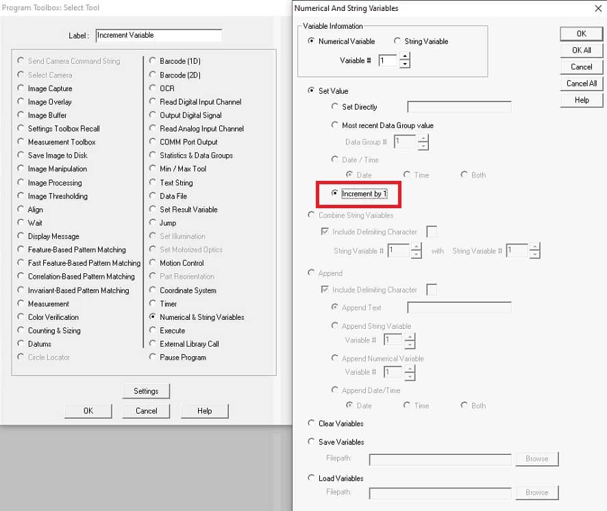
We have added a new “Increment” sub-option for the “Set Value” operation in the Program Toolbox – Numerical and String Variables program step. This “Increment” option is only valid for Numerical Variables. When activated for a Numerical Variable, the selected Numerical Variable will have +1 added to its value. With this, the program can increment a numerical variable under various circumstances during the program flow, and the modified variable can be re-used as needed.

Program Toolbox

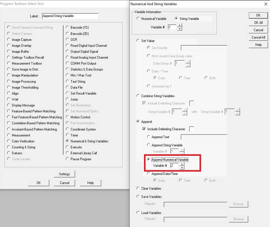
We have also added an option to append a Numerical Variable to an existing String Variable. This may be useful when building label strings for output or creating messages for operators.

Program Toolbox Append Variables

Program Toolbox – “Pause” Settings

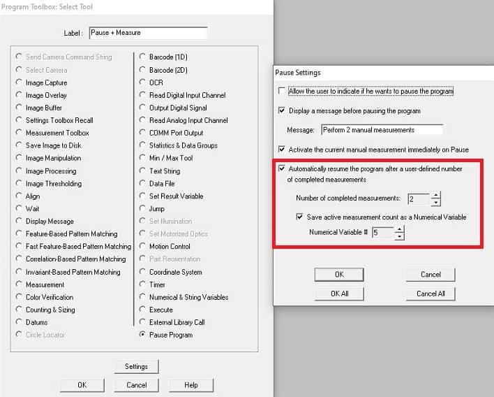
This update enhances the Program Toolbox “Pause” operation with new options.

The option to “Activate the current measurement” will pause the program and immediately start the currently loaded Manual Measurement (as selected from a previous “Measurement Toolbox” program step in the program, for example). This will let an operator immediately start pre-loaded manual measurements, if required as part of an inspection process.

When the “Automatically resume program after a user-defined number of completed measurements” option is enabled, the paused program will resume operation after the user-indicated number of manual measurement/output operations have been completed. Actions that count as a completed measurements are 1) a standard manual measurement with normal termination, and 2) pressing the “Output” button in the “DXF Overlay Translation / Rotation” window if there is a successful output to the Data Group.

Additionally, the Pause Settings can save the number of the currently active measurements being counted as a Numerical Variable. This could be useful when building label strings for Data Group output.

Program Toolbox - new Pause step options

These new Pause Settings options can help streamline any manual operator interactions that may need to occur during an automated program, depending on your application.

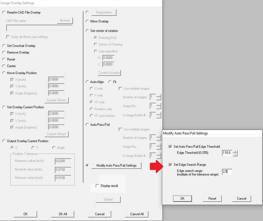
Program Toolbox – Image Overlay – Modify Auto-Pass/Fail Settings

Support has been added to allow modifying additional Auto-Pass/Fail Settings during an automated program. These changes are found in the Program Toolbox – Image Overlay step.

Programs that already use the “Set Auto Pass/Fail Edge Threshold” operation will now find their existing settings included in the new “Modify Auto Pass/Fail Settings” operation button. The option to modify the “Edge Search Range” is also now included.

This new setting may be useful when a single inspection program requires changing the edge search range for different types of measurements or part requirements.

Modify Auto-Pass/Fail Settings

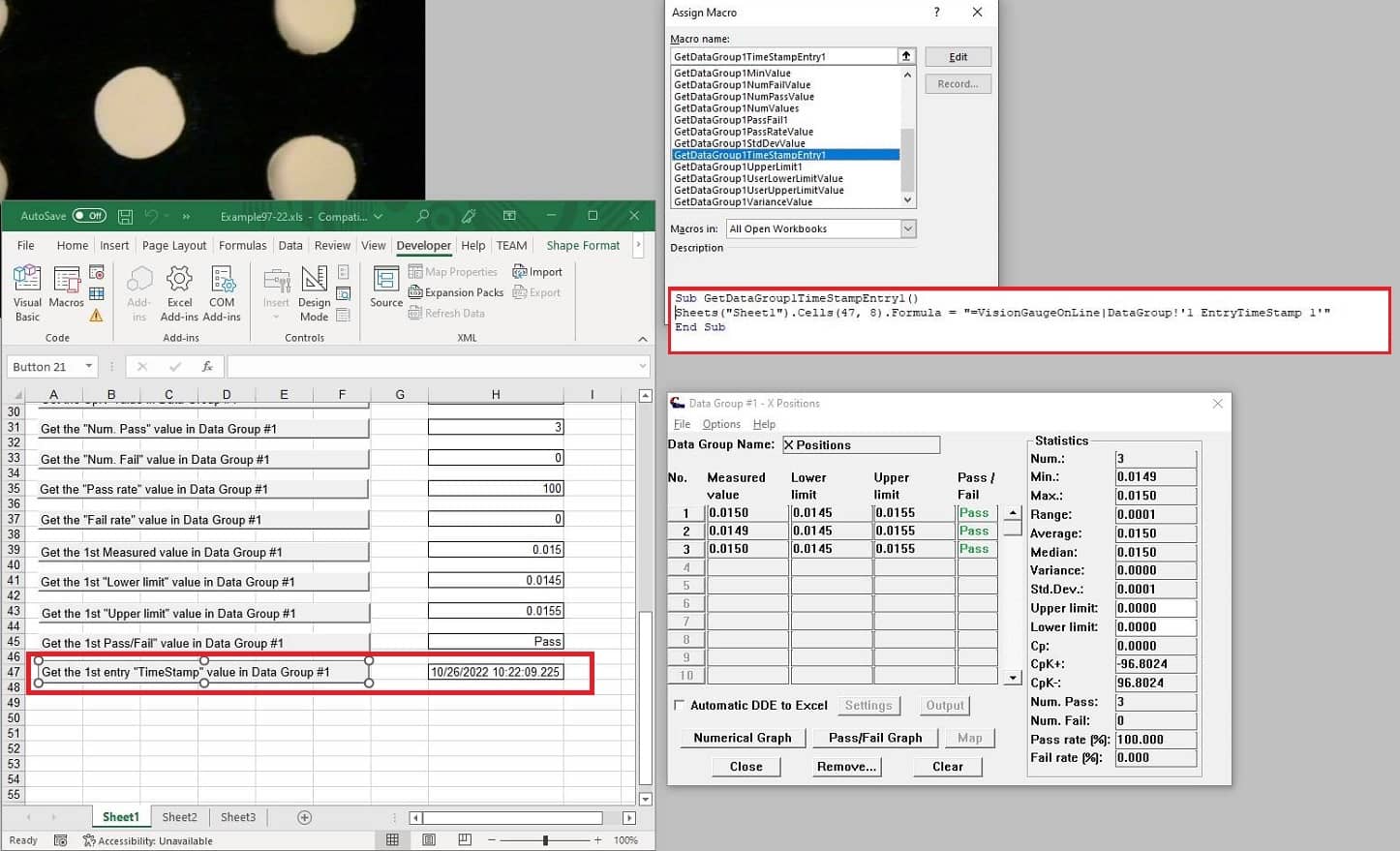
Data Group Entry Timestamps

A timestamp string has been included for each entry that is added into a Data Group. This timestamp string will be accessible for request from DDE commands with the “EntryTimeStamp” keyword and returns the timestamp in the format “Month/Day/Year Hour:Minute:Second.Millisecond”

An example of the formula is: “=VisionGaugeOnLine|DataGroup!’1 EntryTimeStamp 1′”

This command in the “DataGroup” topic requires 3 pieces of information to properly complete in the single quotes:

The number of the Data Group to target

EntryTimeStamp – to obtain the timestamp data for this entry

The entry number in the Data Group to return the timestamp.

The Excel Report example in the C:/vgOnLine/Reports/Excel_Examples/ directory has also been updated (and renamed) with an example of this command transferring the timestamp for the first value in Data Group #1 of VisionGauge OnLine, using the formula shown above.

DDE Retrieval of Data Groups timestamps

Operator Mode – Measurement Mode

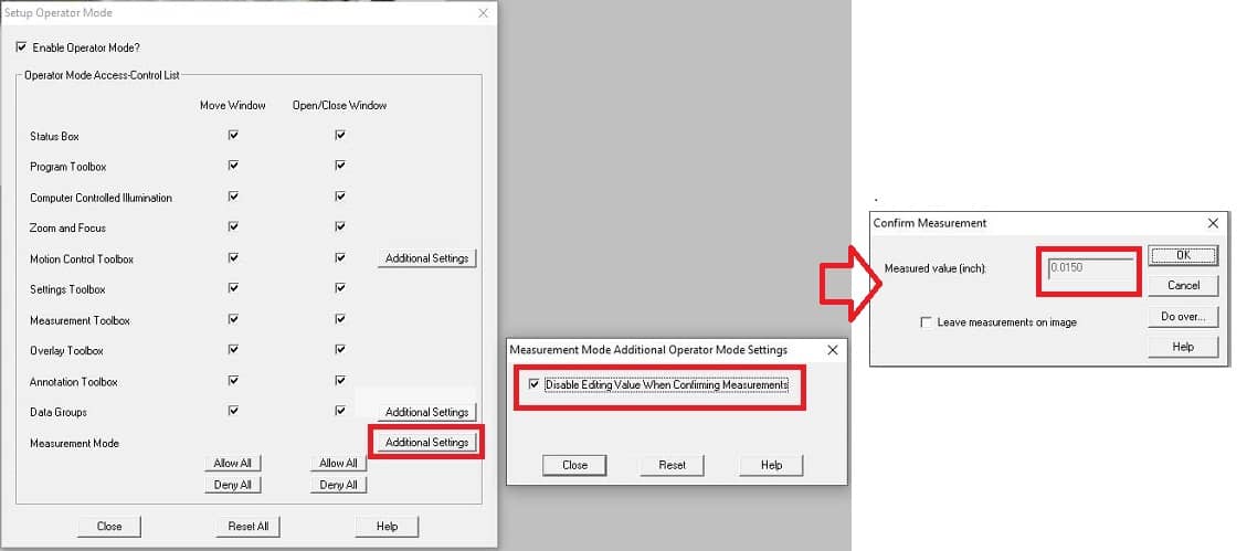
This update adds a new option to the Operator Mode for the “Measurement Mode”. In this setting, an Administrator can select if the ‘edit box’ for manual measurements is disabled when the option to “Allow user to confirm measurements” is selected. If this option is disabled (as it is by default) the user can input any value into this text box and this is the result that would populate the Data Group. By disabling this edit box, the user is still allowed to ‘re-do’ the measurement if they choose, but they cannot manually edit what the measurement result is.

Note that this setting affects the measurement value that is inserted into the Data Group – the annotations created by the user are unaffected.

Operator Mode - Measurement Mode Additional Settings

Operator Mode – Data Group Additional Settings

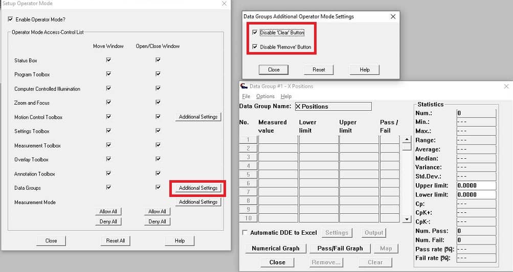
This update includes a new “Special Permissions” option for Data Groups in Operator Mode as “Additional Settings”. This option will allow an Administrator to allow/deny operator access to the “Clear” or “Remove” buttons across all Data Groups, as well as to disable editing the label in Data Groups, if present. As usual, Operator Mode must be turned on to be able to deny access.

Operator Mode - Data Group Additional Settings

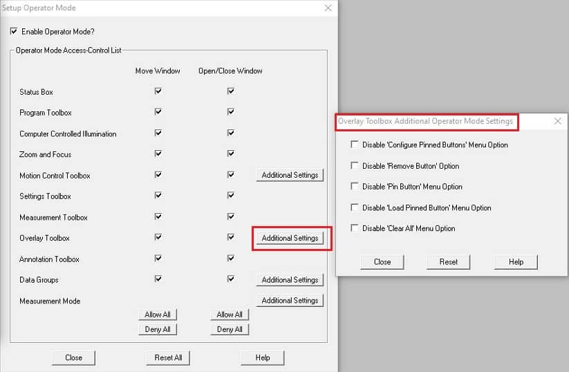
Operator Mode – Overlay Toolbox Additional Settings

We have also added new “Additional Settings” in the Operator Mode for various DXF Overlay Toolbox features, including the ability to enable/disable removing, loading, and pinning button contents.

Operator Mode - Overlay Toolbox Additional Settings

DXF Correspondence File Updates for String/Numerical Variables

This update adds two new options at the end of each DXF Correspondence File entry to load String or Numerical Variables with data. These are 2 new comma-separated options allowing the user to choose the variable type (String/Numerical) and number (currently #1-20) to load, in addition to the data to store. Entire sets of String/Numerical Variables can also be loaded at once with pre-saved files. The loaded String/Numerical Variables are then available to the user during future software actions.

Version 1.3 of the DXF Correspondence File guide is available for download.

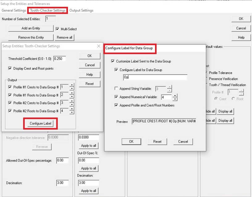
A “Configure Label” option has been added to the Tooth Checker entities setup dialog, allowing the output from this mode to override the default label sent to the Data Group. Options to build this configurable label are:

User-defined label string

String Variable

Numerical Variable

Current Profile # and Crest/Root #

The order in which these options are selected is also recorded, and the Preview edit box displays the current setup during configuration.

Tooth Checker Configure Label for Data Groups

Area and Pathline Measurements

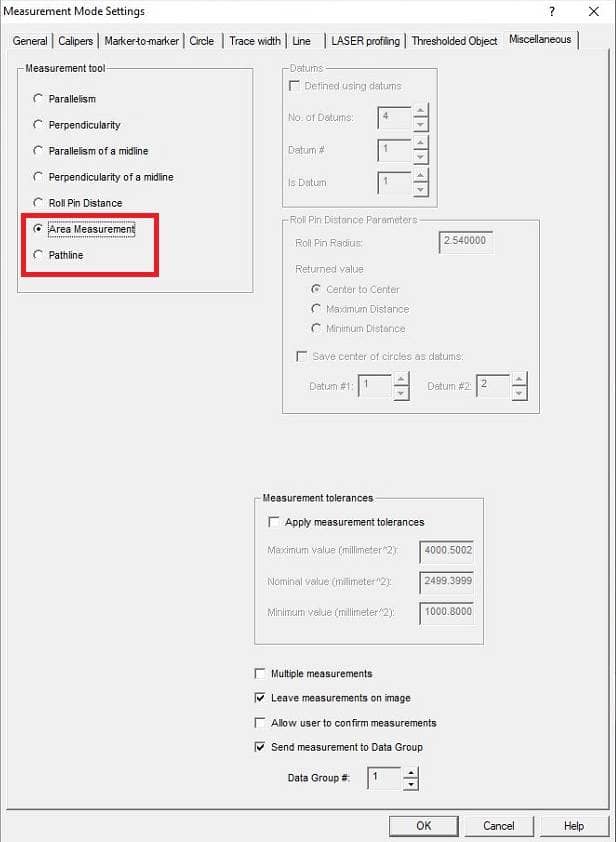
We have added support for Area and Pathline manual measurements in VisionGauge® OnLine. These measurements may be found in Settings – Measurement Mode (or the “Mode” button of the Measurement Toolbox) in the “Miscellaneous” tab.


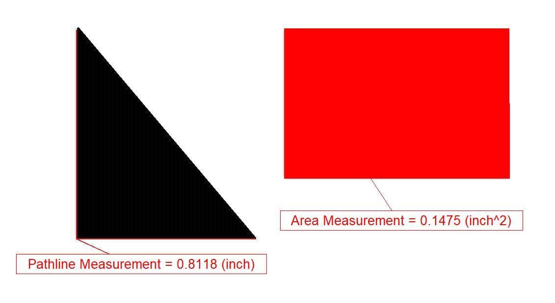
Pathline measurements allow the user to start ‘free-hand’ drawing a path with the cursor, when activated. Click once to start, then move the mouse to trace the path, and click the mouse again to finish. When the measurement is stopped, the total distance traveled along the drawn path is calculated in the current measurement units.

The Area measurement allows the user to outline a closed region on the image and select the region (inside or outside a closed region) for which they want to obtain an area measurement of all pixels included in that region.

Straight-Line and Free-Hand drawing methods are available and can be interchanged during a drawing mode in the dialog box that opens when starting the measurement. After the user has drawn a region, they must select the “Close Area” button which draws a final straight line between the last point selected and the first point. The user must confirm that they accept this closed region before continuing.

After the region is closed, the user must then use the cursor to select the region for which they want to obtain the area measurement:  This can be inside or outside the drawn region. The final value returned is the area in the current measurement units of all pixels included in the selected region.

Area and Pathline manual measurement modes
Area and Pathline measurement examples

Intersection of a Circle and a Line & Orthogonal to a Tangent Line to a Circle Manual Measurements

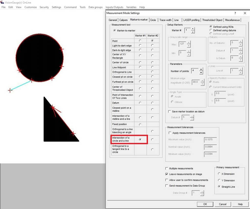
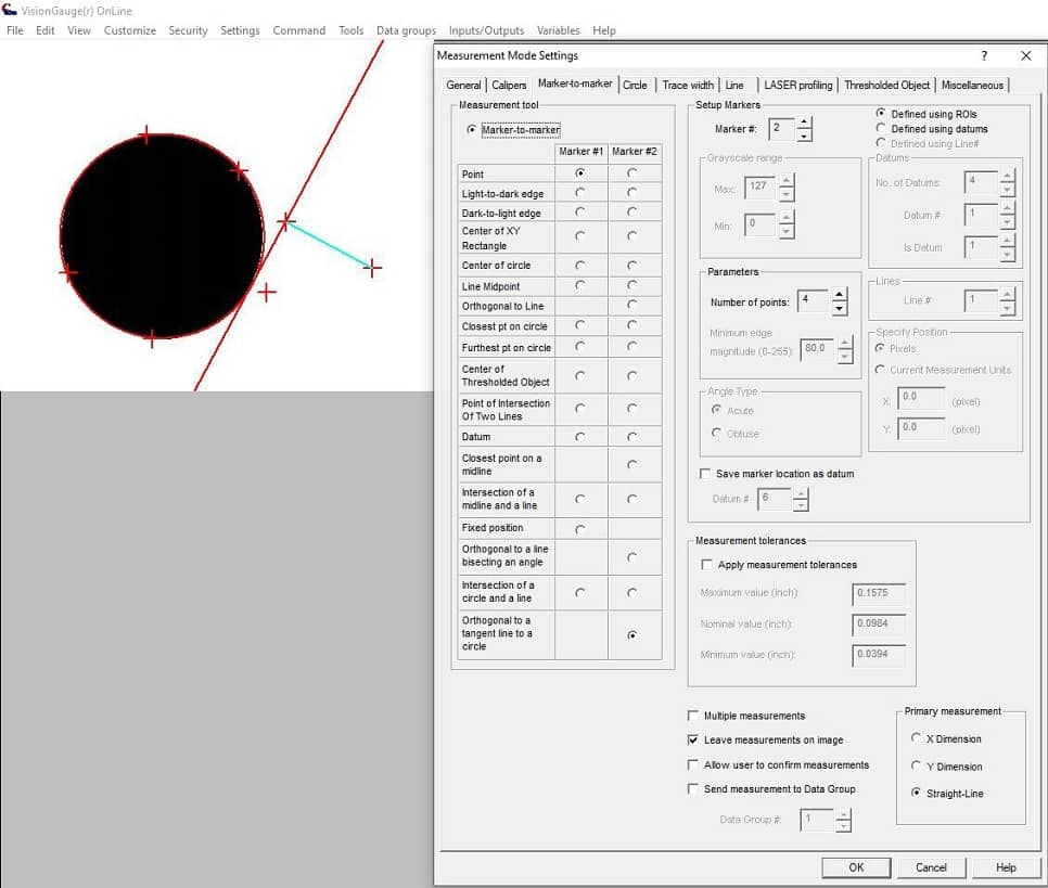
This update adds two new manual measurement tools to the Marker-to-Marker tab Measurement Mode:  Intersection of a Circle and a Line Projection & Orthogonal to a Tangent Line to a Circle


Intersection of a Circle and a Line Projection:

This Marker-to-Marker measurement tool can be defined as both Marker 1 and Marker 2. It requires defining first a circle followed by 2 points to define a line. You can also define this tool with datums. If defining the marker with datums, the minimum number of datums is 5 (3 points minimum to define the circle and 2 points to define the line). When selecting a larger number of datums, the number of points to define the circle must always be the number of datums defined – 2.

If you define the measurement with ROI (default), choose the number of points to define the circle as usual. You will then select that number of measurement points + 2 for the line.

The following rules apply when selecting the intersection point, considering the line selected both as a segment and as a projection:

The measurement will fail if the projection of the line does not intersect with the circle at all, in the direction the line is defined.
If the line projection intersects with the circle at a tangent point, that point will be the marker.
If the line segment intersects with/crosses the edge of the circle at one point, that point will be defined as the marker.
If the line segment intersects with the edge of the circle at two points, the point closest to the 2nd line definition point will be selected as the marker.
Finally, if the line segment does not cross the circle, but the line projection in the direction the line is defined does cross the circle, the first point on the edge of the circle along the line projection will be the marker.

In the following example, the measurement is defined with ROIs and 4 points are being used to define the circle. 2 more points define the line in the direction towards the circle. The line segment defined on the 2 lines points does not cross the circle, but the projection of the line does intersect with the circle, so the first intersection point of the line projection on the circle is returned as the marker.

Intersection of a circle and a line


Orthogonal to a Tangent Line to a Circle

This Marker-to-Marker tool can only be defined as Marker 2. It requires defining first a circle followed by a single point which draws a tangent line at the closest point to the circle. You can also define this tool with datums. If defining the marker with datums, the minimum number of datums is 4 (3 minimum points to define the circle and 1 point to define the tangent line). When selecting a larger number of datums, the number of points to define the circle must always be the number of datums defined – 1.

If you define the measurement with ROIs (default), choose the number of points to define the circle as usual. You will then select that number of measurement points + 1 for the tangent line.

In the following example, 4 points are used to define the circle, and a tangent line on the circle is defined with the last point using the closest point on the circle. The resulting measurement is the closest point on the tangent line to marker 1.

Orthogonal to a Tangent Line to a Circle

“Configure Label” option for Measurement Toolbox buttons

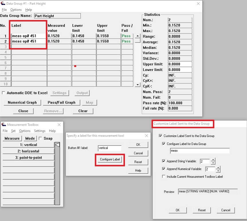
This update adds a new option allowing the user to customize the label that will be output to a Data Group when performing a manual measurement stored in the Measurement Toolbox. Previously, only the Measurement Toolbox label for the activated button would be sent to the Data Group. The new customized label may be sent to the “Label” entry of the targeted Data Group at the same time as the measurement.

This label customization option is available in the “Set” option when specifying the content to save into a Measurement Toolbox button. Users can build a customized label string with the following options:

User-defined label string

String Variable

Numerical Variable

Current Measurement Toolbox label string

The order in which these options are selected is also recorded, and the Preview edit box displays the current setup during configuration.

Measurement Toolbox Label Customization for Data Groups

Restoring Measurement Toolbox Snap Radius and Snap Mode

This update also allows the current snap radius and snap mode to be saved with the Measurement Toolbox. This may be useful for applications that require loading multiple Measurement Toolboxes with different snap criteria.

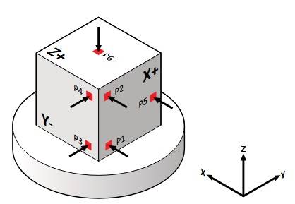
We’ve carried out very significant enhancements to VisionGauge® 6-Point Nest / Reorient Tool, to make it even more widely applicable. Detailed external documentation had been created for this

6-point nest / reorient tool

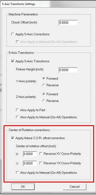
We’ve added cross-polarity corrections for our center-of-rotation corrections

5-axis transforms center of rotation corrections

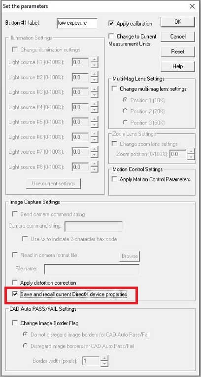
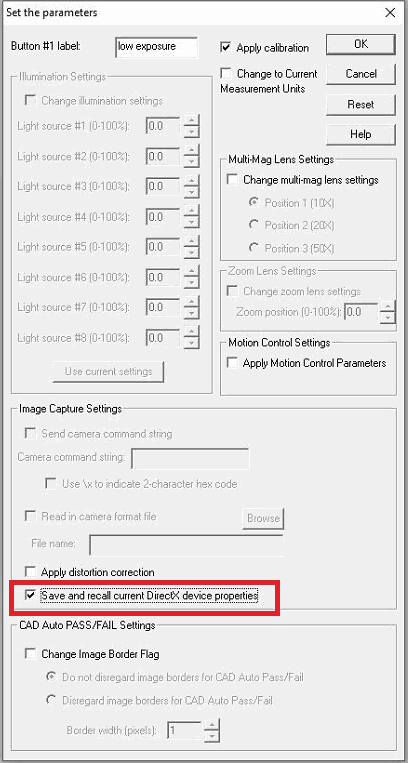
For systems using DirectX-compliant video capture devices, we have added the ability to save and recall DirectX camera properties when shutting down and restarting the software. Examples of these standard properties are exposure, gain, brightness, white balance, etc…

We’ve also added support to allow users to save the currently loaded properties to the Settings Toolbox (for DirectX-supported devices). This is useful to quickly recall device properties without having to manually change these settings.

Saving DirectX image capture settings in the Settings Toolbox

“Distortion Correction” has been added to the list of Factory Locked-out Session items. This is primarily useful for technicians in the field required to carry out distortion correction as part of maintenance.

  • We’ve carried out some enhancements to our “Feature Based Pattern Matching” tool, to enhance its speed & robustness.
  • This update contains a number of enhancements (including significant speedups, etc…) mostly having to do with the software’s ability to read-in tolerances directly from CAD files.
  • We’ve carried out very significant performance enhancements to speedup live video image refresh when working with very (!) large DXF files, especially at high magnification. These new enhancements provide a tremendous speedup in the case of very large files, a medium speedup in the case of medium-size files and very little speedup (if any at all) in the case of very small files (i.e. drawings that fit completely in the field-of-view).

The following fixes have also been made:

  • We have corrected an issue in the Program Toolbox  – Wait program step, when the “Wait for User Input” option may save the input result as a String Variable, even if the option to save the result is unchecked.
  • In the Program Toolbox – Image Overlay step, the “Auto-Align” operation would apply corrections at the end of the step as if an Auto-Align mode with rotation had been selected. This could cause the overlay to move to unintended locations if XY, X-, or Y- only Auto-Align modes were selected, if a default Auto-Align mode had not been previously selected.
  • If a program running in the Program Toolbox was paused, the software could crash when attempting to resume the program if live video was displaying.
  • An issue has been resolved where Auto-Focus may not work in an automated program following a “Pause” step.
  • In the Program Toolbox, the “Run To” program mode will now properly activate a “Pause” operation in the program.
  • We’ve fixed a bug related to carrying over sub-directories from session-to-session.

VisionGauge®’s new “CAD Fitting™” tool


When we introduced VisionGauge®’s patented CAD Auto-Align™ tool, it greatly extended how parts could be inspected. This revolutionary tool gives users the ability to automatically carry out CAD-to-part alignment, very quickly and accurately.

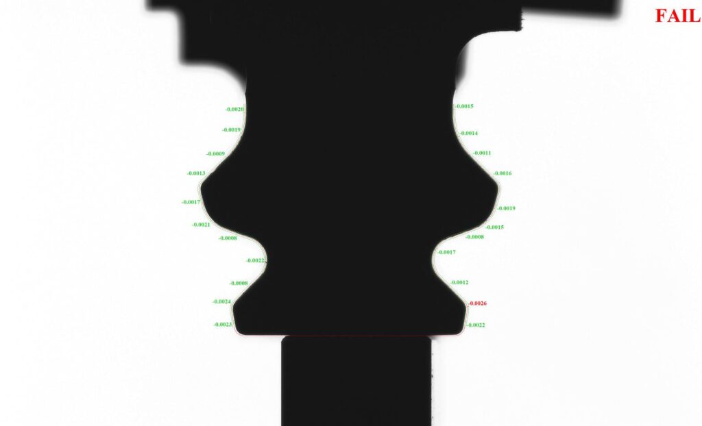
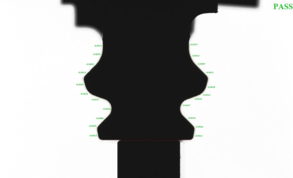
When it is used in conjunction with VisionGauge®’s patented CAD Auto-Pass/Fail™ tool, it allows users to compare a part to its CAD file, completely automatically, with great repeatability & accuracy and absolutely no operator-dependence. There are a great many applications where this is invaluable. The verification of profile and surface tolerances are two very common examples.

We are pleased to announce the release of VisionGauge®’s new CAD Fitting™ tool. This tool is capable of automatically refining the results of CAD Auto-Align™ in some trickier applications to produce even better results.

VisionGauge®’s patented CAD Auto-Align™ tool aligns the CAD nominal to the part at user-specified control sections. It does this in a least-squares sense, i.e. it minimizes the sum of the squared deviations from nominal over all of the control sections.

In most cases, this is ideal. However, there are some situations where it might not be the absolute optimal approach. For example: we can imagine an (extreme) situation where the result of the CAD Auto-Align™ calculation would have the CAD nominal perfectly aligned with the part at all of the control sections except one, at which the part would be just outside the tolerance band. This could lead to a “Fail” result. In this example, the optimal solution might be to slightly modify the alignment (still respecting all of the prescribed constraints) so as to “bring the part back into the tolerance band” at the one control section where this was not the case. This could result in the part slightly “moving away from the CAD nominal” at the other control sections, but still remaining in tolerance at all of these locations. This is what we refer to as “CAD Fitting™” and, in this case, it would transform the result to a “Pass”.

aerospace part CAD Auto-Align results vs CAD Fitting

The results of the CAD Auto-Align™ tool applied on an aerospace part are shown above and those of the CAD Fitting™ tool on the same part are below.

Aerospace part CAD Fitting results

Learn more about VisionGauge®’s new CAD Fitting™ tool.

Contact us with the details of your application!

VisionGauge® OnLine version 15.24 is available for download

VisionGauge® OnLine version 15.24, dated April 22nd, 2022, is available for download.


The following new features and enhancements have been added over the past few versions:


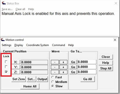
This update adds a Manual Axis Lock which allows users to declare certain axes as ‘Locked’ against manual control in the Motion Control Toolbox. Attempts to manually move an axis/stage that is locked will be prevented (i.e. joystick operations, Motion Control Toolbox +/- buttons, “Go”/”Go All”). The Status Box will receive a message notifying when a locked axis is trying to move.

The “Lock” checkbox can be enabled/disabled in the Motion Control Toolbox’s Display – Lock Settings menu. This feature can be password protected by the VisionGauge® OnLine Security Manager. By default the Manual Axis Lock is reset for all axes when the software is started, but a new option in the Motion Control Toolbox – Startup Settings allows Administrators to determine if these manually locked axes should persist when the software is shutdown/restarted.

This feature could be useful on the fly during difficult inspections when you may want to prevent accidentally changing the focus or the position of specific axes, or Administrators can restrict operator’s manual control over specific axes and rely on automated programs to handle control of these axes.


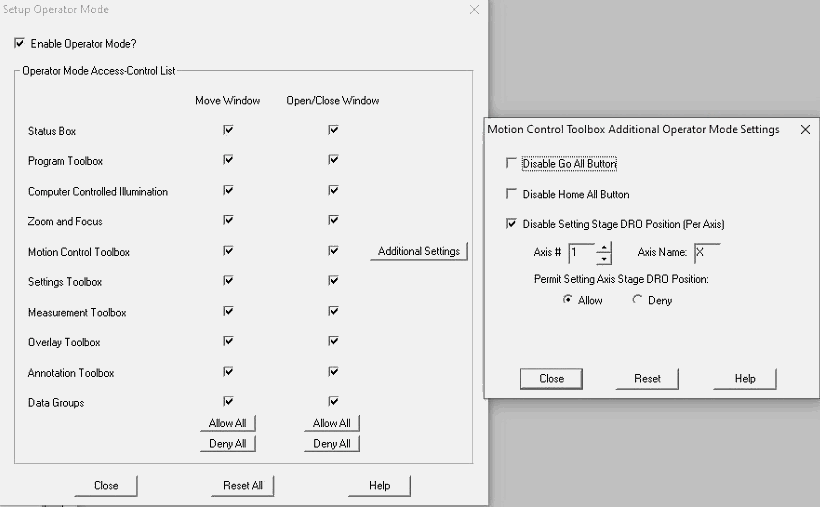
VisionGauge® OnLine’s Operator Mode has been updated to allow Administrators to define additional access control settings for the Motion Control Toolbox, including the following possibilities:

  • disable the Go All button,
  • disable the Home All button,
  • disallow setting positions for specific axes (e.g. Zeroing an axis or setting specific positions in the Motion Control Toolbox)

These new options are not applied by default and must be configured when setting up Operator Mode.


This update also adds the ability to save and recall DirectX compliant camera properties when shutting down and restarting the software. Examples of these standard properties are exposure, gain, brightness, white balance, etc…

We’ve also added support to allow users to save the currently loaded properties to the Settings Toolbox (for DirectX-supported devices only). This is useful to quickly switch/recall device properties without having to manually change these settings.


We’ve enhanced support for Computer Controlled Illumination to allow up to 8 illumination controls for applications with more demanding lighting requirements. Support for a new illumination controller has also been added.


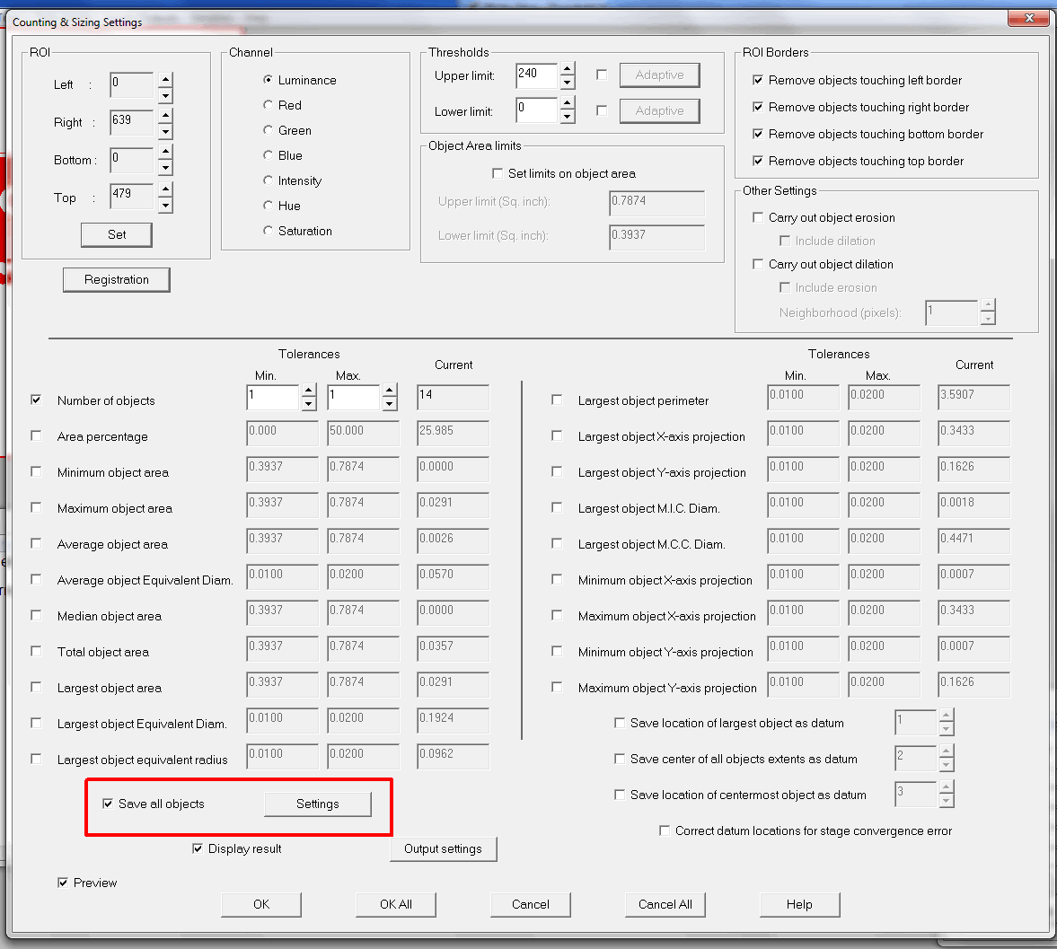
An option has been added to the Program Toolbox – Counting & Sizing Settings to allow the user to save to file information about all objects found from the Counting & Sizing operation.


Various additional performance improvements and enhancements have also been made.


VisionGauge® OnLine version 15.00 / VisionGauge® version 11.00 are available for download

VisionGauge® OnLine version 15.00, dated October 14th, 2021, is available for download.


New features and enhancements have been added over the past few versions:


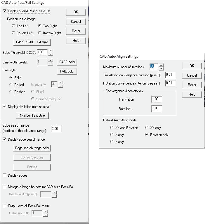
This update moves “Auto-Align” settings previously found in the “CAD Auto Pass/Fail Settings” into a new “CAD Auto-Align Settings” window, accessible from the Overlay Toolbox alongside the “Auto Pass/Fail Settings”.

The CAD Auto-Align Settings include a new parameter to save a default Auto-Align Mode (e.g. X-only, Y-only, XY + Rotation, etc.) when Live Video is activated. XY + Rotation alignment is set by default. The option is saved with each CAD file’s .apf file when configured. This allows users to load different CAD files, each with its own default Auto-Align Mode pre-selected.


The CAD Auto-Pass/Fail Settings also include a new set of default values when setting up Control Sections. These default values are applied when a new control section is added, which can make short work of setting up multiple control sections with the same tolerances, display deviations, and more. You can also use the “Apply to All” button to change the settings for all currently configured control sections.


We have also greatly improved the motion convergence time when running programs VisionGauge® OnLine’s Program Toolbox when the Watchdog option enabled and an E-Stop is connected to the motor drives. This ultimately contributes to motion programs running even faster without sacrificing positioning accuracy. In some of our test cases, we experienced programs with many Motion Control steps running up to 40% faster!


VisionGauge® OnLine’s live overlay image refresh rate has been improved when displaying complex DXF file with a large number of entities. These improvements are particularly noticeable when viewing a relatively small field-of-view compared to the full scope of the overlay being drawn, e.g at high magnifications or very large overlays.


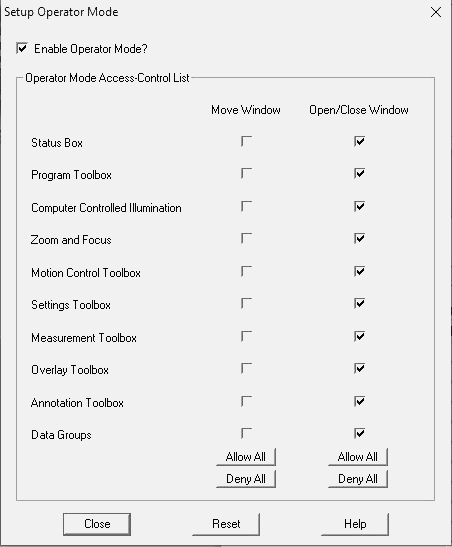
VisionGauge® OnLine now includes a new “Operator Mode” feature. Operator Mode is designed to let Administrators setup a repeatable environment for their operators that limits the operator control over 1) moving windows and/or 2) opening and closing windows when this mode is enabled. Administrators can customize control by choosing to Allow or Deny these Move and Open/Close window operations for individual tools in the Security menu:

Operator Mode is disabled by default so this update will not make user interface changes until Operator Mode is explicitly enabled. After Operator Mode has been enabled, control is automatically restricted based on the Administrator’s configurations when VisionGauge® OnLine starts up. Control over setting up Operator Mode is password protected and factory locked-out. A new option has been added to the Single-Session Factory Lock-Out procedure to permit modifying Operator Mode during a single session of VisionGauge® OnLine.

Additional feature and menu restrictions may be added with future updates of the software.


We have also added new ‘Cancel All’ buttons to the Program Toolbox’s Setup windows. This button is useful for quickly cancelling out of all changes to a program step and returning control directly to the Program Toolbox itself, instead of the Program Toolbox settings setup window.


We’ve enhanced support for certain DirectX/DirectShow compliant cameras that do not list their full resolution compatibilities. This update applies to both VisionGauge® and VisionGauge® OnLine. Previously when using these devices, when users tried to save a certain resolution as default, the maximum resolution would be displayed instead. Now these resolutions are all able to be properly saved and restored, as well as the camera framerate and bitdepth.


VisionGauge® OnLine version 13.99 and VisionGauge® version 10.91 are available for download.


VisionGauge® OnLine version 13.99, dated February 24th, 2020, is available for download.


The following enhancements have been made over the last few update versions:


VisionGauge® OnLine users may now specify the type of image that can be collected in a Data Group. Either the ‘raw’ image (without annotations or measurements) or the ‘displayed’ image (with measurements and ROIs) can be stored in a Data Group. It could be particularly useful to view the displayed image from a measurement if the Data Group shows a ‘Fail’ for a certain result to see inspect what went wrong.

Data Group options - Collecting results images


VisionGauge® OnLine’s IO Monitoring/Conditions feature allows users to a) configure specific output channels on which to output a signal when a certain condition is met during a operation of the software and to b) select an input channel to monitor for a signal to perform a specific action in the software.

When both Input Monitoring and Output Conditions are combined, VisionGauge® OnLine can be remotely automated by a robot or a controller that issues commands to the software. The Remote Program Communications feature was originally developed for communication by commands sent through TCP/IP or over a COM port, but this IO Monitoring/Conditions update allows either simplified automation using exclusively Digital IO’s or expands upon the existing Remote Program Communication feature-set with additional command/verification methods.

Input Monitoring allows digital input channels to be periodically scanned for a signal. When the target channel is activated, the software will perform specific actions. VisionGauge® OnLine presently supports the following Input signal monitoring actions:

  • Loading a program
  • Starting a program
  • Stopping a program
  • Pausing a program
  • Clearing Program Errors (when operating in ‘Silent Mode’)
  • Stop/Prevent Stage Motion
  • Check VisionGauge® OnLine Software Active Status (make sure the software is still alive and responding)
Input Monitoring - VisionGauge OnLine

Output Conditions allow the user to configure digital output channels to be activated when certain conditions are met during software operation. VisionGauge® OnLine presently supports outputting a signal when the following conditions are met or actions are performed:

  • Program is Loaded and Ready to Run
  • Program is Running
  • Program is Paused
  • Program Error
  • Silent Mode is Enabled
  • Program is Completed
  • Program Result (Pass/Fail)
  • In-Position (Stage is at a certain position)
Output Conditions - VisionGauge OnLine

It is possible to reserve output channels so programs and operators cannot accidentally output on those channels.

A new quick access button, accessible from the “Customize – User Interface” menu, also allows Input Monitoring and Output Conditions to be started or stopped by an operator.

Full documentation to describe how to use these input and output signals to work remotely (e.g. via a cell controller), is available.


VisionGauge® OnLine programs can take advantage of our True Position measurement tool. Our approach to True Position allows a user to define a Nominal feature whose position is compared to the Actual occurrence of that feature. Features are defined using datums that have been set in previous program steps. Nominal features can be defined using either Cartesian or Polar coordinates, which is convenient for different types of applications. Nominal features can also be offset using Basic Dimensions in the current measurement units.

VisionGauge® Online presently supports Cylindrical (point location) and Non-Circular (line) features of size, and the Nominal tolerance zone is displayed along with the Actual feature location. As with all VisionGauge® Online measurements, results, including a Pass/Fail result, can be output to Data Groups and other reporting options.

True Position measurement for Cylindrical Features of Size
True Position measurement for Non-Circluar Features of Size

Follow the link for more information about our True Position measurement software tool.


This update also adds support for Laser Angle Correction – to address the situation where a system’s lasers for measurements are not perfectly at 45 degrees with the stage.


Various fixes, performance enhancements, and improvements in memory management.


VisionGauge® version 10.91 is available for download.

This update includes support for a newer USB computer controlled illumination module, fully compatible with Windows 10.


VisionGauge® OnLine version 12.80 and VisionGauge® version 10.79 are available for download.


VisionGauge® OnLine version 12.80, dated January 18th, 2018, is available for download.

VisionGauge® version 10.79, dated January 18th, 2018, is available for download.


Both VisionGauage and VisionGauge OnLine have been updated with the ability to save and recall the last-set camera format settings (e.g. resolution) for DirectX compliant video capture devices. This update also applies to those systems that control multiple DirectX video acquisition devices at once. To change the resolution during a session of either VisionGauge or VisionGauge OnLine, access the “Settings – Image capture device format” menu and set the target resolution. The software will save this resolution and automatically restore it the next time you start the software.

This enhancement for DirectX video capture devices is included starting in VisionGauge OnLine’s current version 12.80 and in VisionGauge’s current version 12.79.


Also included in this update for VisionGauge OnLine is the ability to output a string variable directly to a data group through the Program Toolbox – Text String settings:

Output string variables directly to Data Groups in VisionGauge OnLine.